
Low-voltage transformer area power supply loop abnormity analysis method based on impedance calculation

A power supply loop and impedance calculation technology, which is applied in the field of abnormal analysis of power supply loops in low-voltage stations based on impedance calculation, can solve problems such as inability to meet actual use, inaccurate loop impedance, and large current dispersion, so as to improve work efficiency and users. Satisfaction, improve the reliability of power supply, and avoid the effect of disconnection failure

Active Publication Date: 2019-07-23
STATE GRID ZHEJIANG ELECTRIC POWER +1
View PDF6 Cites 12 Cited by
  • Summary
  • Abstract
  • Description
  • Claims
  • Application Information

AI Technical Summary

Problems solved by technology

[0003](1) This patent only discloses an impedance loop method when the electric energy meter current is at point Ib. In actual use, the user current has relatively large dispersion, so this method It cannot meet the actual use, and the formula also has the case that the impedance is calculated to be less than zero
[0004](2) Due to the fact that there are multiple users using electricity at the same time, there will be different degrees of influence on the circuit calculation of each household. The circuit impedance calculated by the existence of this patent inaccurate, not applicable

Method used


Image

  • Low-voltage transformer area power supply loop abnormity analysis method based on impedance calculation
  • Low-voltage transformer area power supply loop abnormity analysis method based on impedance calculation
  • Low-voltage transformer area power supply loop abnormity analysis method based on impedance calculation

Examples


Embodiment Construction

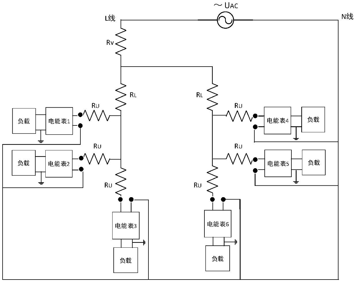
[0031] The technical solution of the present invention will be further described in detail below in conjunction with the accompanying drawings. like figure 1 Shown is the structure diagram of the power supply circuit. Among them, the impedance of the power supply loop includes the internal impedance of the transformer R V , The line impedance R before the power supply line enters the house L and the line impedance R between the household line and the energy meter U , that is, the equivalent impedance of the front-end circuit of the electric energy meter, and the present invention analyzes the abnormality of the power supply circuit in the low-voltage station area by calculating the impedance of the power supply circuit.

[0032] like Figure 4 Shown, the present invention comprises the following steps:

[0033] 1) Obtain the data of the electric meter, including the current value i and the voltage value u at time t;

[0034] 2) When |i1-i0|>s0 and |i1-i0|>s1, then add th...


PUM


Abstract

The invention discloses a low-voltage transformer area power supply loop abnormity analysis method based on impedance calculation, and relates to the field of power grid power supply analysis. The current electricity stealing condition is difficult to discover, the electricity stealing causes certain loss to an electric power company, one-by-one investigation is carried out by sending manpower tothe field, and the cost is high. The invention comprises the following steps: acquiring ammeter data, when |i1-i0|>s0 and |i1-i0|>s1, then adding the vector into an impedance calculation record table;when the record number in the record table is greater than or equal to the set value n, then deleting the vector with the minimum value of |i1-i0| from the record table to add current vector into therecord table, arranging the record in the sequence from large to small according to the current break variable (|i1-i0|), and calculating impedance, the impedance calculation result=|(u0-u1)| / |(i1-i0)|; and when the calculated impedance value is larger than the impedance set value, analyzing the user. According to the technical scheme, the fault type can be found and positioned in advance, on-site maintenance is arranged in time, the low-voltage loop disconnection fault can be avoided through impedance online monitoring, the equipment fault time is reduced, and the working efficiency and theuser satisfaction are improved.

Description

technical field [0001] The invention relates to the field of grid power supply analysis, in particular to a method for analyzing abnormality of a power supply circuit in a low-voltage station area based on impedance calculation. Background technique [0002] The current situation of electricity theft is difficult to find. The electricity theft has caused certain losses to the power company. It is costly to go to the site to check one by one by manpower. In order to solve this problem, the publication number is CN107167662, and the name is a method for measuring the user loop impedance by a smart meter, and the impedance loop method when the electric energy meter current is at point Ib is used to analyze the electricity stealing situation. But there are following problems in this technical scheme: [0003] (1) This patent only discloses an impedance loop method when the electric energy meter current is at point Ib. In actual use, the user current is relatively discrete, so t...

Claims


Application Information

Patent Timeline
IPC IPC(8): G01R22/06G01R11/24G01R27/16
CPCG01R22/066G01R11/24G01R27/16
Inventor 王伟峰陆春光裘华东麻吕斌
Owner STATE GRID ZHEJIANG ELECTRIC POWER
Learn More