Ground fault detection system and detection method

A ground fault and detection system technology, applied in the fault location, measurement power, measurement device and other directions, can solve problems such as ground faults, and achieve the effects of avoiding losses, accurate positioning, and safe and reliable detection process.

Inactive Publication Date: 2019-07-23
GUIZHOU POWER GRID CO LTD
View PDF6 Cites 5 Cited by
  • Summary
  • Abstract
  • Description
  • Claims
  • Application Information

AI Technical Summary

Problems solved by technology

[0002] At present, most of the power supply systems of my country's distribution network and large industrial and mining enterprises use low-current grounding grids. When the system supplies power, it is easy to cause grounding faults due to natural disasters or equipment aging.

Method used


Image

  • Ground fault detection system and detection method
  • Ground fault detection system and detection method
  • Ground fault detection system and detection method

Examples


Embodiment 1

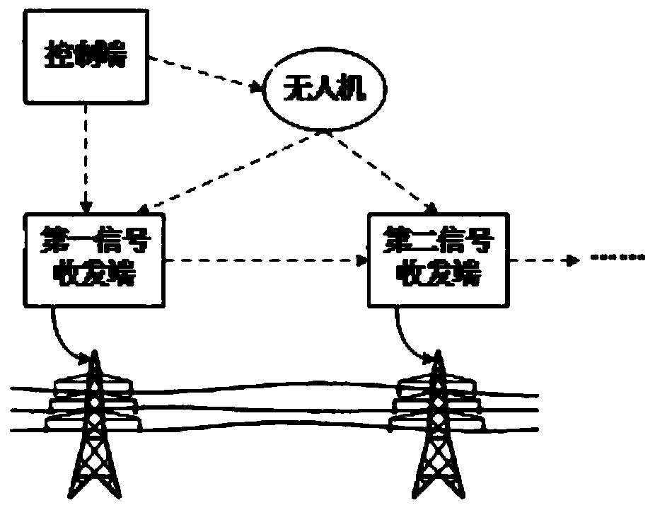
[0033] Embodiment 1: A ground fault detection system, including a plurality of signal transmitting and receiving terminals, a control terminal, and an unmanned aerial vehicle.

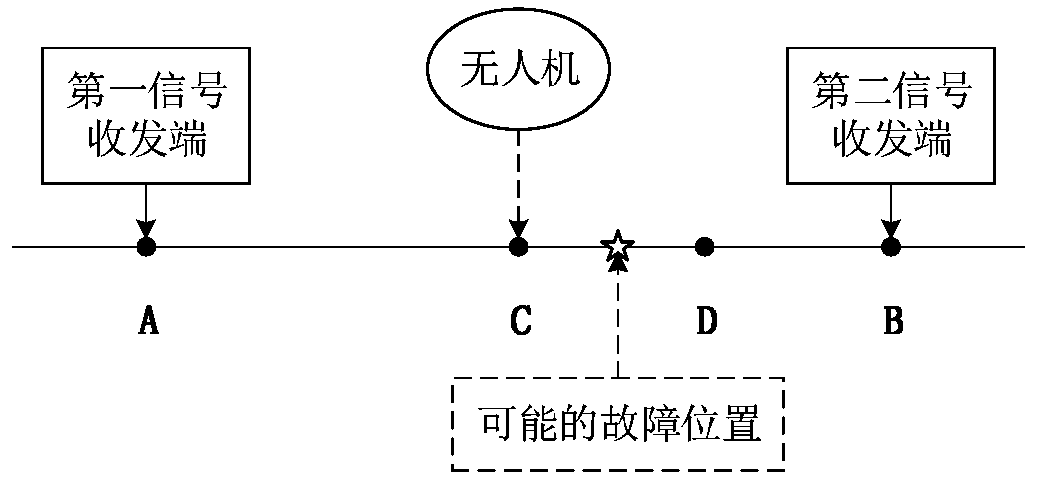
[0034] The signal transceiver end is arranged in the power line along the circuit transmission direction, and is used to inject a test signal into the power line, and receive the feedback information of the test signal detected by the adjacent back-end signal transceiver end; When a certain signal transceiver end does not receive the feedback information from the adjacent back-end signal transceiver end, it is determined that the power line section between the signal transceiver end and the adjacent back-end signal transceiver end is a fault section where a ground fault occurs, and The location information of the faulty section is fed back to the control terminal.

[0035] The control terminal is connected with the signal transceiver terminal and the UAV signal, and is used to control signal transmissi...

Embodiment 2

[0037] Embodiment 2: A ground fault detection system, including a plurality of signal transmitting and receiving terminals, a control terminal, and an unmanned aerial vehicle.

[0038] The signal transceiver end is arranged in the power line along the circuit transmission direction, and is used for injecting a test signal into the power line, and receiving the feedback information of the test signal detected by the adjacent back-end signal transceiver end; When a signal transceiver end does not receive the feedback information from the adjacent back-end signal transceiver end, it is determined that the power line section between the signal transceiver end and the adjacent back-end signal transceiver end is a fault section where a ground fault occurs, and The location information of the faulty section is fed back to the control terminal.

[0039] The control terminal is connected with the signal transmitting and receiving terminal and the UAV signal, and is used to control sign...

Embodiment 3

[0050] Embodiment 3: A ground fault detection system, including a plurality of signal transmitting and receiving terminals, a control terminal, and an unmanned aerial vehicle.

[0051] The signal transceiver end is arranged in the power line along the circuit transmission direction, and is used to inject a test signal into the power line, and receive the feedback information of the test signal detected by the adjacent back-end signal transceiver end; When a certain signal transceiver end does not receive the feedback information from the adjacent back-end signal transceiver end, it is determined that the power line section between the signal transceiver end and the adjacent back-end signal transceiver end is a fault section where a ground fault occurs, and The location information of the faulty section is fed back to the control terminal.

[0052] The control terminal is connected with the signal transceiver terminal and the UAV signal, and is used to control signal transmissi...


PUM


Abstract

The invention relates to the technical field ofelectric power fault detection, and discloses a ground fault detection system and method. The ground fault detection system comprises a plurality of signal transceiving terminals in signal connection with one another, a control terminal, and a drone. The method comprises the steps that a test signal is injected into anelectric power circuit through the signal transceivingterminals, a back end signal transceivingterminal adjacentto the signal transceivingterminals detects the test signal and sends feedback information to the signal transceiving terminals, so that the signal transceiving terminals determine a faulty section where a ground fault occurs and feeds back position information of the faulty section to the control terminal; andthen thecontrol terminal injects the test signal into the faulty section by controlling the drone to accurately detect the faulty section and locate the fault location where the ground fault occurs. The procedure of the ground fault detection method is automatically executed by the control terminal, the drone, and the signal transceivingterminalsarranged in the electric power circuit,the detection processis safe and reliable, the fault location where the ground fault occurs can be located more quickly, efficiently, and accurately, so that the ground fault can be eliminated as early as possible,and more significant losses are avoided.

Description

technical field [0001] The invention relates to the technical field of power fault detection, and relates to a ground fault detection system cabinet and a detection system. Background technique [0002] At present, most of the power supply systems of my country's distribution network and large industrial and mining enterprises use low-current grounded power grids. When the system supplies power, it is easy to cause ground faults due to natural disasters or equipment aging. [0003] When a single-phase ground fault occurs in a small-current grounded power grid, the ground voltage of the non-faulted phase will rise to the normal voltage times, if an intermittent arc ground fault occurs, it will also cause a higher overvoltage, which poses a threat to the weak link in the power grid. If the ground fault exists for a long time, it will lead to the occurrence of short circuit fault, therefore, the fault line should be found and eliminated as soon as possible. Contents of the ...

Claims


Application Information

Patent Timeline
Patent Type & Authority Applications(China)
IPC IPC(8): G01R31/02G01R31/08G01R29/08G01R29/12
CPCG01R31/08G01R29/0871G01R29/12G01R31/50
Inventor 李华鹏张容菠杨忠国良彬王云吴飞林红孙学宝方雪淞郭刀张青李定强李永辉杨瑞景杜建国补敏文峰肖小兵姜浩文忠进杜雪王大龙窦陈
Owner GUIZHOU POWER GRID CO LTD
Why Eureka
Try Eureka