Video signal receiver, video signal receiving module, and video signal transmitting and receiving system
A technology for video signal transmission and video signal application, which is applied in CCTV systems, components of TV systems, transmission systems, etc., and can solve the problem that central computing processors and image sensors do not have the ability to send and receive video signals and frame signals.
- Summary
- Abstract
- Description
- Claims
- Application Information
AI Technical Summary
Problems solved by technology
Method used
Image

Examples
no. 1 Embodiment approach
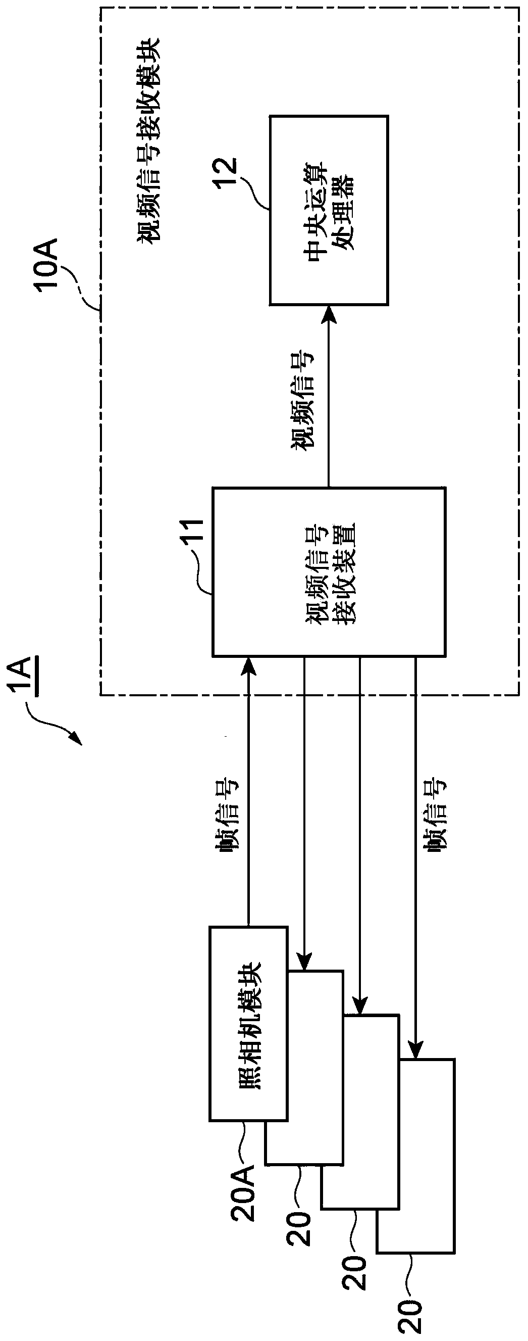
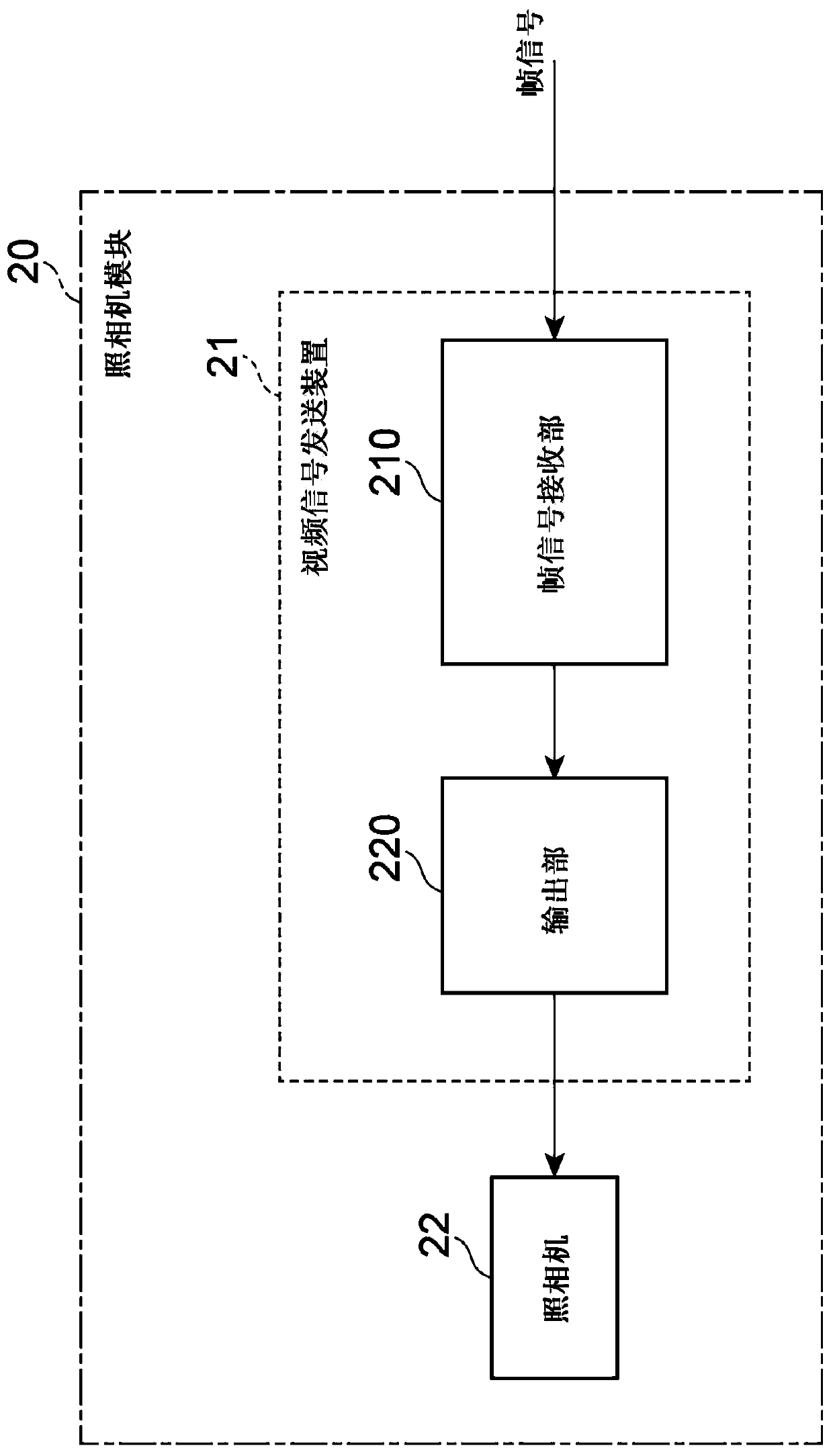
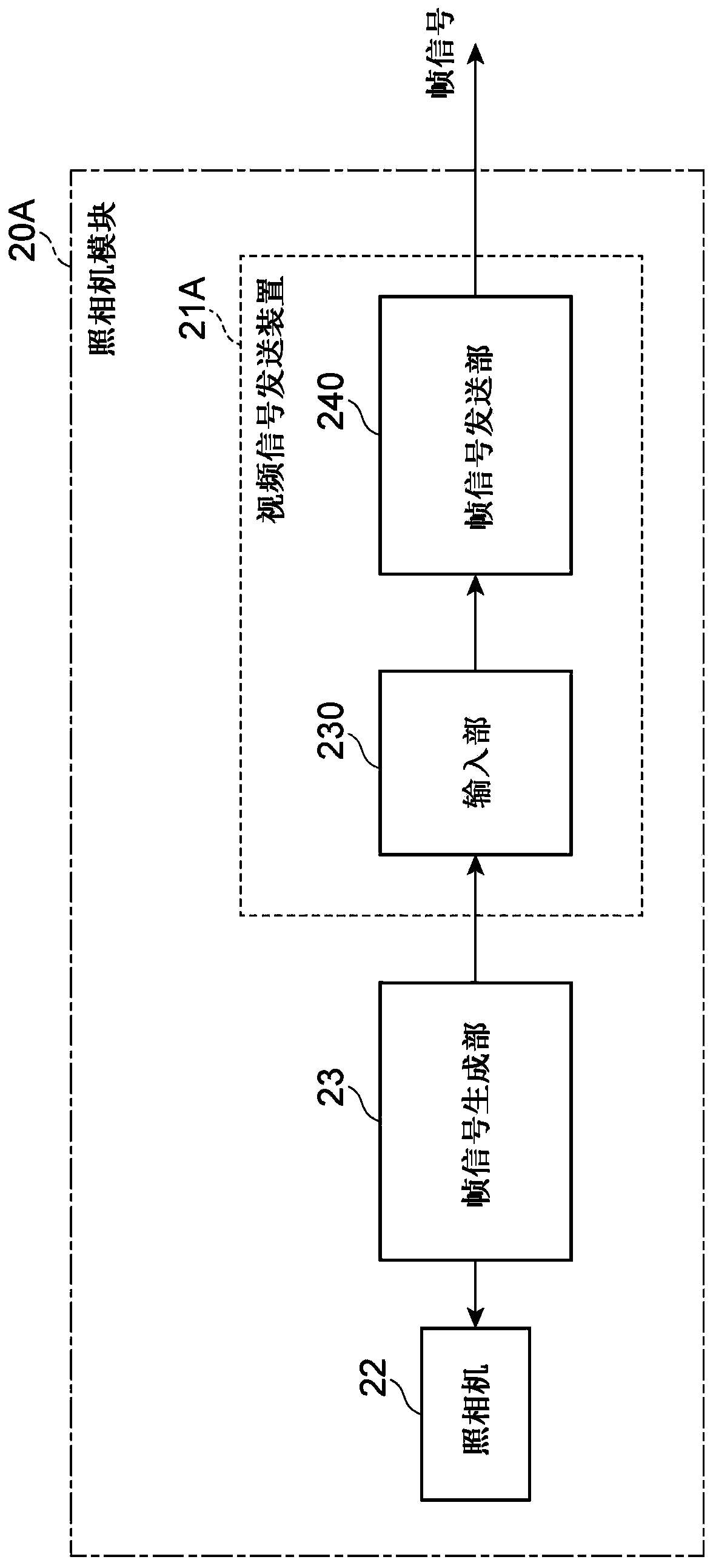
[0039] figure 1 It is a diagram showing the configuration of the video signal transmission and reception system 1A of the first embodiment. The video signal transceiving system 1A has a video signal receiving device 11 in a video signal receiving module 10A, a video signal transmitting device 21 in a camera module 20, and a specific video signal transmitting device 21A in a specific camera module 20A. The video signal receiving module 10A includes a video signal receiving device 11 and a central processing unit 12. Such as figure 2 As shown, the camera module 20 includes a video signal transmitting device 21 and a camera 22. Such as image 3 As shown, the specific camera module 20A includes a specific video signal transmitting device 21A, a camera 22, and a frame signal generating unit 23.
[0040] in figure 1 Here, the video signal receiving device 11 has a configuration in which one specific camera module 20A and three camera modules 20 are connected, but the number of camera...
no. 2 Embodiment approach
[0052] Figure 5 It is a diagram showing the configuration of a video signal transmission and reception system 1B according to the second embodiment. The video signal transceiving system 1B has a first video signal receiving device 11A and a second video signal receiving device 11B in a video signal receiving module 10B, a video signal transmitting device 21 in a camera module 20, and a specific video signal in a specific camera module 20A Transmission device 21A. The video signal receiving module 10B includes a first video signal receiving device 11A, a second video signal receiving device 11B, and a central processing unit 12. The camera module 20 has figure 2 The structure shown. The specific camera module 20A has image 3 The structure shown.
[0053] in Figure 5 Here, the video signal receiving module 10B includes a first video signal receiving device 11A and two second video signal receiving devices 11B, but the number of second video signal receiving devices 11B includ...
no. 3 Embodiment approach
[0060] Figure 8 It is a diagram showing the configuration of a video signal transmission and reception system 1C according to the third embodiment. The video signal transceiver system 1C has a first video signal receiving device 11C and a second video signal receiving device 11D in a video signal receiving module 10C, a video signal transmitting device 21 in a camera module 20, and a specific video signal in a specific camera module 20A Transmission device 21A.
[0061] The first video signal receiving device 11C is connected to the specific video signal transmitting device 21A via a signal line, and receives the video signal transmitted from the specific video signal transmitting device 21A. Further, the first video signal receiving device 11C receives the frame signal transmitted from the specific video signal transmitting device 21A through the frame signal receiving unit 110, and outputs the received frame signal to each second video signal receiving device 11D through the ...
PUM
 Abstract
Description
Claims
Application Information
 - R&D
- Intellectual Property
- Life Sciences
- Materials
- Tech Scout
- Unparalleled Data Quality
- Higher Quality Content
- 60% Fewer Hallucinations
Browse by: Latest US Patents, China's latest patents, Technical Efficacy Thesaurus, Application Domain, Technology Topic, Popular Technical Reports.
© 2025 PatSnap. All rights reserved.Legal|Privacy policy|Modern Slavery Act Transparency Statement|Sitemap|About US| Contact US: help@patsnap.com