Clamping and pressing device for pipe connection

A pipe and pressing technology, which is applied in the directions of feeding devices, positioning devices, storage devices, etc., can solve the problems such as the inability to realize the automatic work of the pressing device, the inability to improve the working efficiency of the tube pressing, and the reduction of the structural flexibility of the pressing device. , to achieve the effect of automating work, improving flexibility, and shortening the process of processing

Inactive Publication Date: 2019-07-26
陈特
View PDF7 Cites 5 Cited by
  • Summary
  • Abstract
  • Description
  • Claims
  • Application Information

AI Technical Summary

Problems solved by technology

[0004] During the processing of the pipe, it needs to be compressed and sealed. The so-called pipe compression connection is a way to realize the connection and sealing of the pipe and the pipe fitting through cold extrusion. It is to insert the pipe with the sealing ring in advance. The socket of the pipe fittings exerts circumferential pressure on the connecting section of the socket from the outside, so that the connecting section of the socket together with the inserted pipe is sunken and deformed, and then locked and locked, so as to realize the effective sealing connection between the pipe and the pipe fitting. The existing pipe pressing device structure is inconvenient to realize automatic loading and unloading of pipes, reduces the flexibility of the pressing device structure, increases the labor intensity of workers, and cannot realize the automatic work of the pressing device and make it impossible to make the pipe fittings The socket is automatically loaded, and it needs to be added manually, which cannot improve the work efficiency of pipe clamping

Method used


Image

  • Clamping and pressing device for pipe connection
  • Clamping and pressing device for pipe connection
  • Clamping and pressing device for pipe connection

Examples


Embodiment Construction

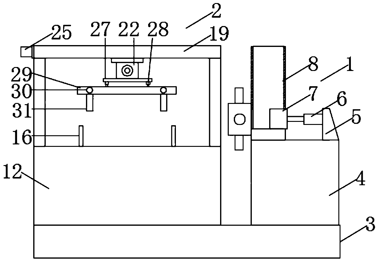
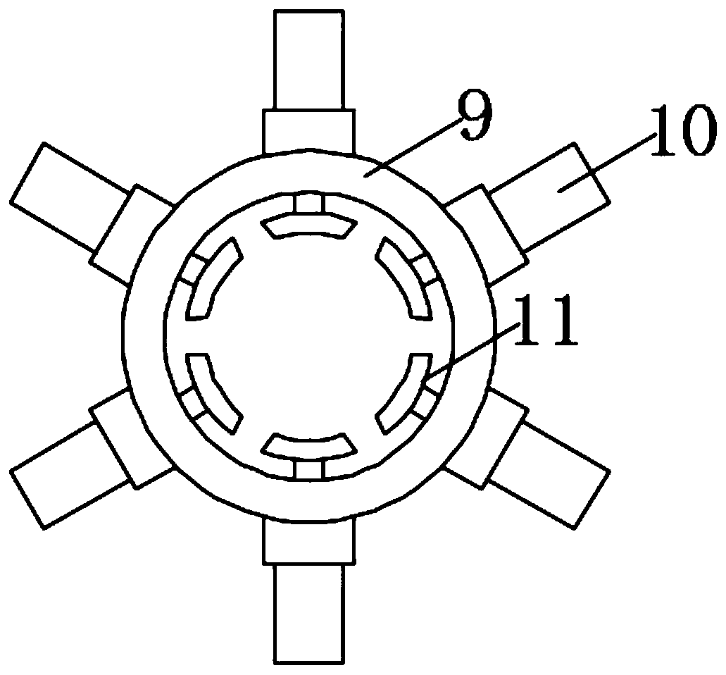
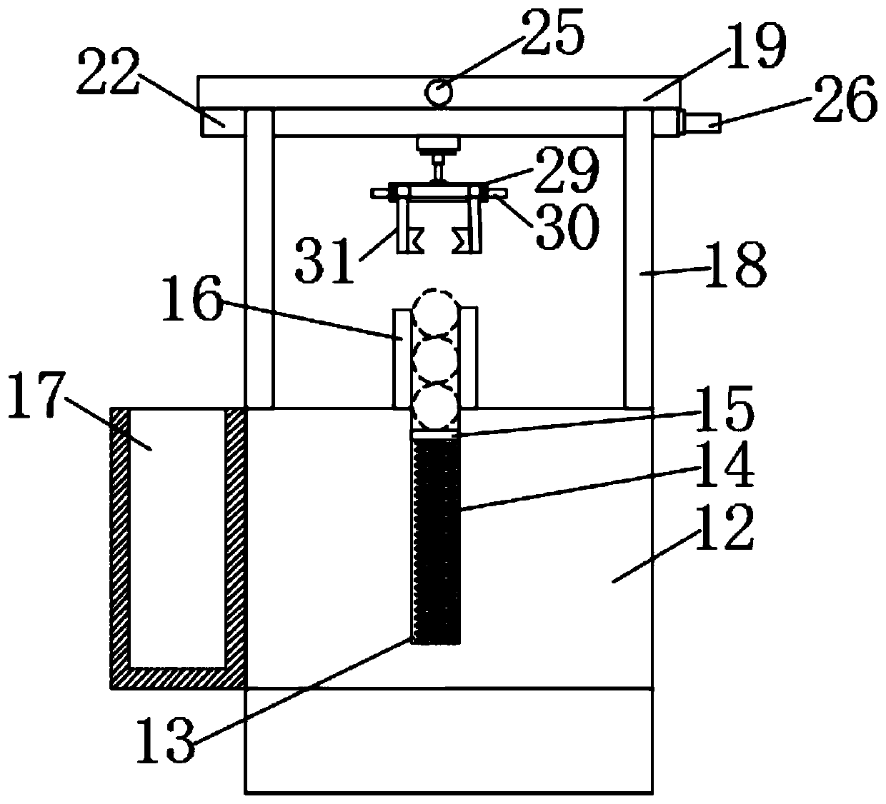
[0026] like Figure 1-5 As shown, this specific embodiment adopts the following technical solutions: a pressing device for pipe material connection, including a pressing mechanism 1, a feeding mechanism 2 and a fixed base 3, and one end of the top of the fixed base 3 is provided with a feeding material Mechanism 2, the end of the top of the fixed base 3 away from the feeding mechanism 2 is provided with a clamping mechanism 1, and the clamping mechanism 1 consists of a fixed table 4, a fixed block 5, a feeding cylinder 6, a feeding push block 7, and a material storage mechanism. The chute 8, the clamping ring 9, the hydraulic cylinder 10 and the clamping block 11 are composed, one end of the top of the fixed base 3 is fixedly connected with a fixed table 4, and one end of the top of the fixed table 4 is fixedly connected with a fixed block 5, and The other end of the top of the fixing table 4 is fixedly connected with a material storage chute 8 , the side of the fixing block 5...


PUM


Abstract

The invention discloses a clamping and pressing device for pipe connection. The clamping and pressing device for pipe connection comprises a clamping and pressing mechanism, a feeding mechanism and afixed base. The feeding mechanism is arranged at one end of the top of the fixed base. The clamping and pressing mechanism is arranged at the end, far away from the feeding mechanism, of the top of the fixed base. The clamping and pressing mechanism is composed of a fixed platform, a fixed block, a feed cylinder, a feeding push block, a storage sliding chute, a clamping and pressing ring, hydraulic cylinders and clamping and pressing blocks. One end of the top of the fixed base is fixedly connected with the fixed platform. The clamping and pressing device for pipe connection realizes automaticfeeding and discharging of pipes through the feeding mechanism, a second motor and a first motor. The structural flexibility of the clamping and pressing device is greatly improved. The labor intensity of workers is reduced. Automated operation of the clamping and pressing device is realized. The clamping and pressing device for pipe connection can conduct automatic feeding on sockets of the pipes through the storage sliding chute and the feeding push block without manual adding. The machining process of pipe clamping and pressing is shortened. The working efficiency of the pipe clamping andpressing is improved.

Description

[0001] Technical field: [0002] The invention belongs to the technical field of mechanical equipment, and particularly relates to a pressing device used for pipe connection. [0003] Background technique: [0004] In the process of pipe processing, it needs to be pressed and sealed. The so-called pipe press connection is a way to realize the connection and sealing of pipes and pipe fittings by cold extrusion. The socket of the pipe fitting exerts circumferential pressure on the connecting section of the socket from the outside, so that the connecting section of the socket together with the inserted pipe material is concavely deformed and then locked and locked, so as to realize the effective sealing connection between the pipe material and the pipe fitting. The existing structure of the pipe pressing device is inconvenient to realize the automatic loading and unloading of the pipe, reduces the flexibility of the pressing device structure, increases the labor intensity of the w...

Claims


Application Information

Patent Timeline
Patent Type & Authority Applications(China)
IPC IPC(8): B21D39/04B21D43/00B21D43/02B21D43/10B21D43/20B21D45/02
CPCB21D39/046B21D43/006B21D43/027B21D43/105B21D43/20B21D45/02
Inventor 陈特
Owner 陈特
Why Eureka
Try Eureka