
A hand-held grinder

A kind of grinding machine and hand-held technology, which is applied in the direction of grinding frame, portable grinding machine, grinding machine tool parts, etc., can solve the problems of operator fatigue, solder joint grinding quality reduction, etc., so as to change the grinding area and ensure grinding Depth and precision, the effect of precise grinding

Active Publication Date: 2020-05-22
温岭市豪基机床附件有限公司
View PDF18 Cites 2 Cited by
  • Summary
  • Abstract
  • Description
  • Claims
  • Application Information

AI Technical Summary

Problems solved by technology

[0004] As in the above-mentioned disclosed technology, since the solder joint is slightly higher than the surface of the workpiece, in the actual solder joint grinding operation, the operator needs to control the distance that the grinding wheel moves to the workpiece. When the moving distance is too large, pits are formed on the surface of the workpiece. When the moving distance is too small, there are still solder joints on the surface of the workpiece, which needs to be polished again. Therefore, skilled operators are required to perform grinding. However, long-term grinding will still cause fatigue of the operator, which will reduce the quality of solder joint grinding on the workpiece surface.

Method used


Image

  • A hand-held grinder
  • A hand-held grinder
  • A hand-held grinder

Examples


Embodiment 1

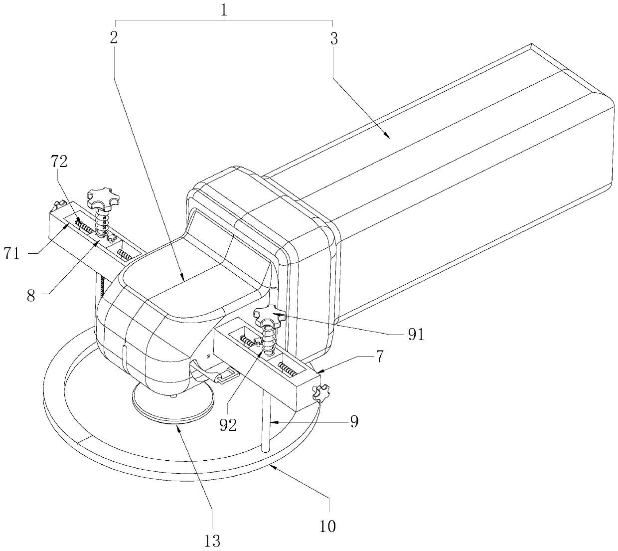
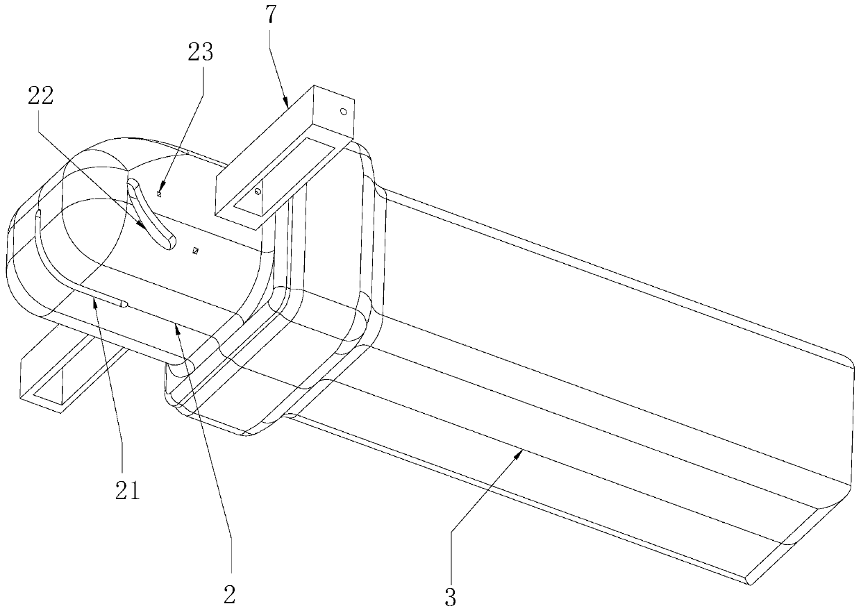
[0034] Such as figure 1 As shown, a hand-held grinding machine includes a frame 1 and a grinding wheel 13. The frame 1 includes a hand-held part 3 and a mounting part 2. A motor 4 is arranged in the hand-held part 3, and a drive shaft is provided at the rotating end of the motor 4. 41, the grinding wheel shaft 5 and the transmission gear set for connecting the grinding wheel shaft 5 and the driving shaft 41 are rotated in the installation part 2, and the grinding wheel 13 is coaxially fixed on the grinding wheel shaft 5, the motor 4 is started, and the transmission gear is used to The group makes the grinding wheel shaft 5 drive the grinding wheel 13 to rotate, and the lower end surface of the grinding wheel 13 is close to the welding spot on the workpiece, so as to realize the purpose of grinding the welding spot.

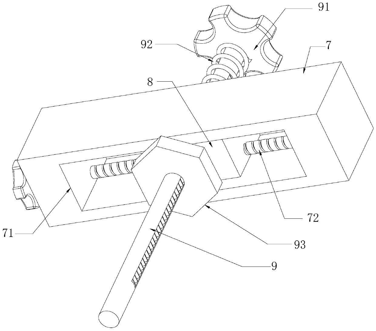
[0035] Such as figure 1 and figure 2 As shown, mounting seats 7 are arranged on both sides of the width direction of the mounting part 2, and the mounting seat...

Embodiment 2

[0046] The difference between embodiment two and embodiment one is:

[0047] Such as Figure 5 As shown, a rack 94 is provided on the lifting rod 9 and along its vertical direction, a gear 11 is rotated on the slide 8, and the gear 11 is engaged with the rack 94, and a gear 94 is rotated on the slide 8 Screw mandrel 12, screw mandrel 12 is meshed with the side of gear 11 away from rack 94, screw mandrel 12 is extended and arranged along vertical direction, is provided with handle at the upper end of screw mandrel 12, turns handle, makes leading screw drive gear 11 to rotate, The gear 11 further drives the rack 94 and the lifting rod 9 to move until the lower end surface of the positioning plate 10 is flush with the grinding surface of the grinding wheel 13 .


PUM


Abstract

The invention relates to a handheld grinding machine. The handheld grinding machine comprises a rack and a grinding wheel arranged on the rack, and further comprises mounting seats arranged on the rack, wherein lifting rods penetrate through the mounting seats in the vertical direction in a sliding mode, a positioning board is arranged at the lower ends of the lifting rods, a locking assembly forlimiting movement of the corresponding lifting rod is arranged on each mounting seat, and the lower end face of the positioning board is flush with the lower end face of the grinding wheel. By slidingthe lifting rods, the lower end face of the positioning board and the lower end face of the grinding wheel are attached to the upper end face of a workpiece, and during grinding, the grinding wheel is close to the welding spot until the lower end of the positioning board abuts against the surface of the workpiece, so that the condition that the welding spot is excessively or rarely grinded is avoided, and the grinding precision is improved.

Description

technical field [0001] The invention relates to the field of workpiece surface grinding, in particular to a hand-held grinding machine. Background technique [0002] The full name of electric grinding machine is reciprocating electric polishing grinding machine (also known as file grinding machine), which is widely used in finishing and surface polishing treatment in mold industry. [0003] Existing notification number is the Chinese patent of CN207431947U, and it discloses a kind of hand-held grinding device that is used for ceramic grinding burr, comprises handle, motor and metal protection cover, and described handle handle side is provided with motor, and described motor There is an auxiliary handle fixing rod on the side, an auxiliary handle is arranged on one side of the auxiliary handle fixing rod, a metal protective cover is arranged on one side of the motor, a rotating shaft is arranged inside the metal protective cover, and the surface of the rotating shaft is prov...

Claims


Application Information

Patent Timeline
Patent Type & Authority Patents(China)
IPC IPC(8): B24B23/02B24B41/02B24B9/04B24B55/00B24B47/12
CPCB24B9/04B24B23/02B24B41/02B24B47/12B24B55/00
Inventor 林海军
Owner 温岭市豪基机床附件有限公司
Learn More