Method for sharpening broach for processing turbine wheel disc blade root groove

A blade root groove and steam turbine technology, which is applied to broaches, metal processing equipment, broaching machines, etc., can solve problems such as the decrease in the life of broaches, the decrease in the accuracy of blade root grooves in steam turbine discs, and the decrease in working stability, and achieve gear lift The effect of uniform weight, prolonging the grinding cycle, and smooth and uniform changes

Active Publication Date: 2014-10-08
HARBIN TURBINE
View PDF6 Cites 7 Cited by
  • Summary
  • Abstract
  • Description
  • Claims
  • Application Information

AI Technical Summary

Problems solved by technology

[0008] The purpose of the present invention is to provide a method for grinding the broach for processing the root groove of the steam turbine disk, so as to solve the problem that the working stability of the existing broach for the blade root groove of the steam turbine disk is reduced after grinding, resulting in a decrease in the service life of the broach , the problem that the accuracy of the machined steam turbine wheel blade root groove decreases

Method used


Image

  • Method for sharpening broach for processing turbine wheel disc blade root groove
  • Method for sharpening broach for processing turbine wheel disc blade root groove
  • Method for sharpening broach for processing turbine wheel disc blade root groove

Examples


specific Embodiment approach 1

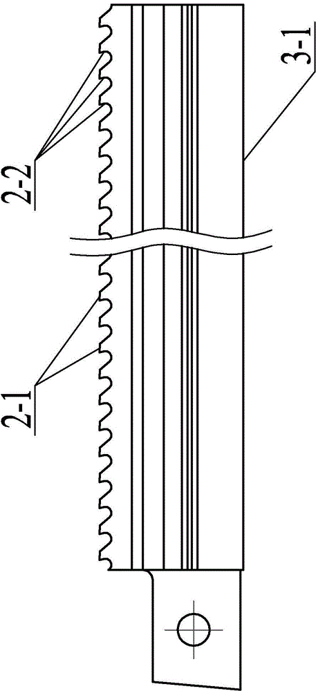
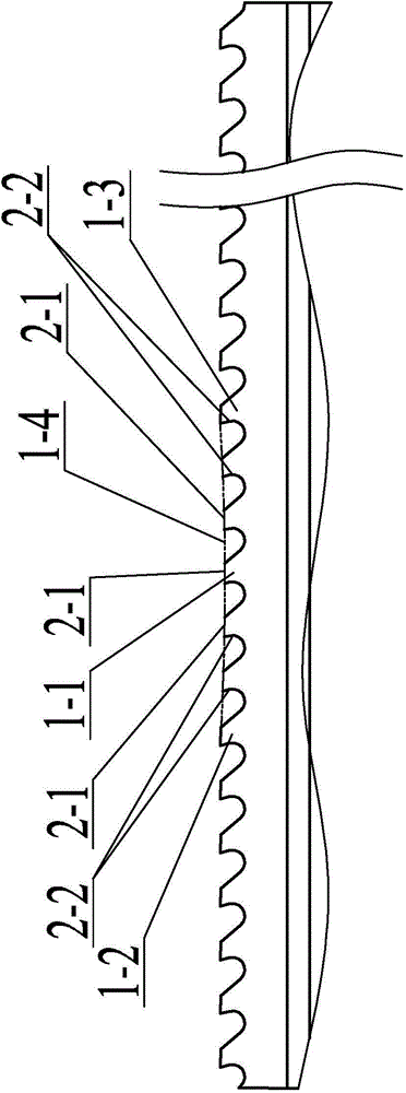
[0019] Specific implementation mode one: combine Figure 1 to Figure 3 Illustrate, the described method of this embodiment is as follows:

[0020] Step 1, install and fix; use the bottom surface 3-1 of the broach as the positioning surface, and install the broach on the broach grinder;

[0021] Step 2: Grind and quantify the amount of grinding on the unsnapped tooth or the tooth with wear less than 0.3 mm; measure the highest point of the flank 2-1 of the tooth with a meter to find out the chipping or Mark the cutter teeth 1-1 with a wear amount of 0.3mm to 1mm, record the tooth lift amount of the cutter teeth with the wear amount less than 0.3mm, and then grind the rake face 2-2 of the cutter teeth with the wear amount less than 0.3mm, and grind The amount is 0.10mm to 0.15mm, so that the highest point of the flank 2-1 of the cutter tooth with the wear amount less than 0.3mm is reduced, the feed amount of the grinding wheel is 0.01mm, and the speed of the grinding wheel is 3...

specific Embodiment approach 2

[0026] Specific implementation mode two: combination Figure 1 to Figure 3 Explain that the bottom surface 3-1 of the broach described in step 1 of this embodiment is the positioning surface, and the dial gauge or dial gauge is installed and fixed on the grinding wheel arm of the broach grinder, and the dial gauge or dial gauge The contact point is in contact with the bottom surface 3-1, so that the grinding wheel arm moves and the pointer swing range of the dial indicator or dial gauge is checked in real time to measure whether the bottom surface 3-1 is positioned accurately, so that the positioning error of the bottom surface 3-1 is within 0.01mm .

[0027] The undisclosed technical features in this embodiment are the same as those in the first embodiment.

specific Embodiment approach 3

[0028] Specific implementation mode three: combination Figure 1 to Figure 3 Explanation, in the step 2 of the present embodiment, measure the highest point of the cutter tooth flank 2-1 with a meter; install and fix the dial indicator or the dial indicator on the grinding wheel arm of the broach grinder, and the dial indicator or the dial indicator The contact point of the contact is in contact with the flank 2-1 of the cutter tooth, so that the grinding wheel arm is moved and the pointer swing range of the dial indicator or dial indicator is checked in real time to measure the highest point of the flank 2-1 of the cutter tooth.

[0029] The undisclosed technical features in this embodiment are the same as those in the first or second specific embodiment.


PUM


Abstract

The invention relates to a method for sharpening a broach for processing a turbine wheel disc blade root groove, and relates to a method for sharpening the broach, for solving the problems that the working stability of a conventional sharpened broach of the turbine wheel disc blade root groove is degraded, the service life of the broach is shortened, and the precision of the processed turbine wheel disc blade root groove is degraded. The method comprises the following steps: 1, mounting the broach onto a broach grinding machine; 2, measuring a highest point of a rear cutter surface of a cutter tooth, grinding a front cutter surface of a cutter tooth of which the abrasion is smaller than 0.3 mm, wherein the feeding amount of a grinding wheel is 0.01 mm, the rotation speed of the grinding wheel is 3000rpm, and polishing the grinding wheel once after every 100 cutter teeth are polished; 3, firstly, confirming and calculating the grinding amount expected by the front cutter surface of the marked cutter tooth, and forming a concave surface between 2-3 first cutter teeth and a top point of the rear cutter surface from the cuter teeth to 2-3 second cutter teeth. The method is used for sharpening the broach for processing the turbine wheel disc blade root groove.

Description

technical field [0001] The invention relates to a broach grinding method. Background technique [0002] The machining accuracy of the blade root groove of the steam turbine disk is high, so the accuracy of the broach used for the machining of the blade root groove of the steam turbine disk is also high. In order to ensure the broaching accuracy of the blade root groove of the steam turbine disk, the broach after grinding and chipping must be ground every time 3 to 4 blade root grooves of the steam turbine disk are processed, and the working stability of the broach decreases after grinding , The broach is very easy to jump when broaching after grinding, resulting in a decrease in the stability and life of the broach, and a decrease in the precision of the processed steam turbine wheel blade root groove. [0003] The main reasons for the decline in the stability of the broach after grinding are as follows: [0004] 1. In terms of personnel: The feed rate of the grinding whee...

Claims


Application Information

Patent Timeline
Patent Type & Authority Applications(China)
IPC IPC(8): B24B3/16
CPCB24B3/16
Inventor 刘剑孙盛丽栗磊齐莹莹王志臣
Owner HARBIN TURBINE
Why Eureka
Try Eureka