A substrate fixing device

A technology for fixing devices and substrates, applied in metal material coating process, vacuum evaporation plating, coating and other directions, can solve the problems of short service life, broken glass substrate, less use of the clamping part, etc., to improve the yield , Improve stability and reduce the effect of pickling times

Active Publication Date: 2021-11-23
WUHAN CHINA STAR OPTOELECTRONICS TECH CO LTD
View PDF0 Cites 0 Cited by
  • Summary
  • Abstract
  • Description
  • Claims
  • Application Information

AI Technical Summary

Problems solved by technology

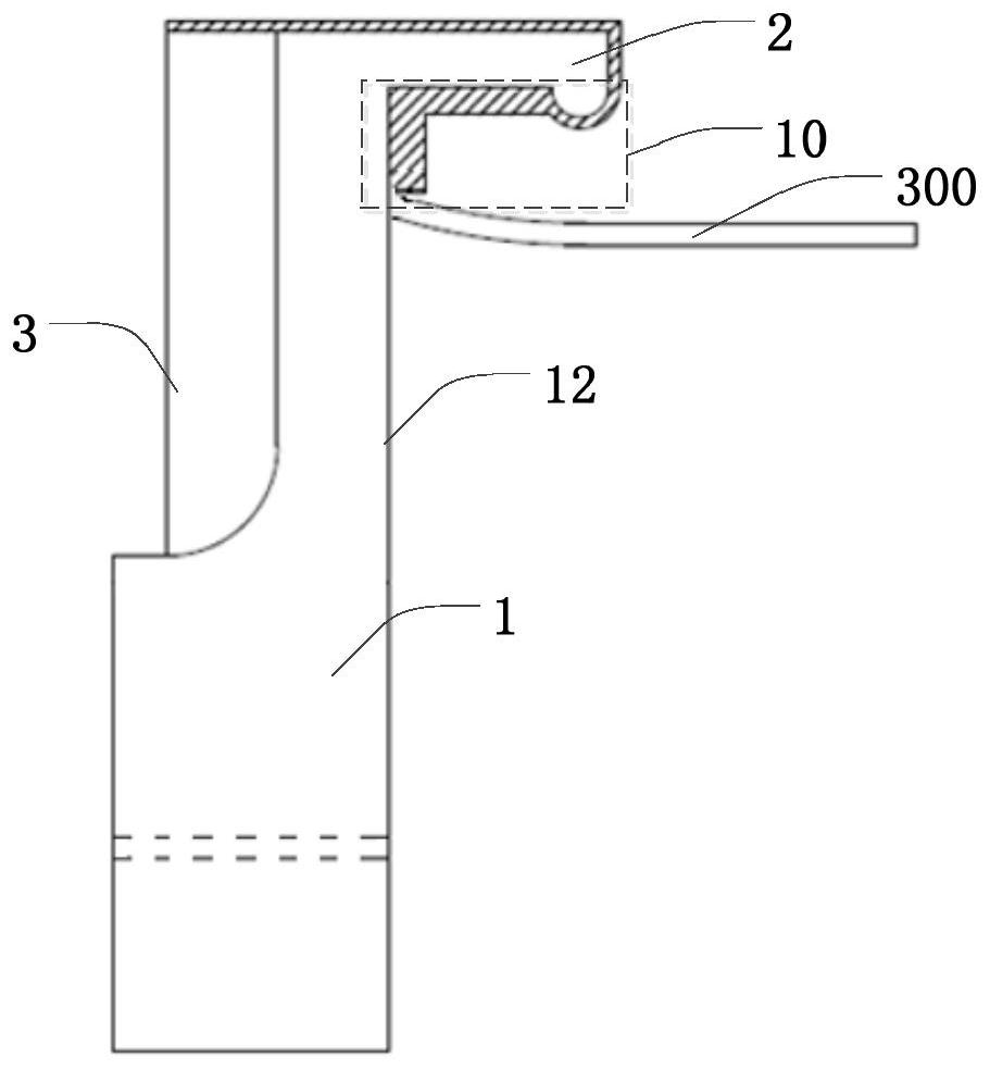
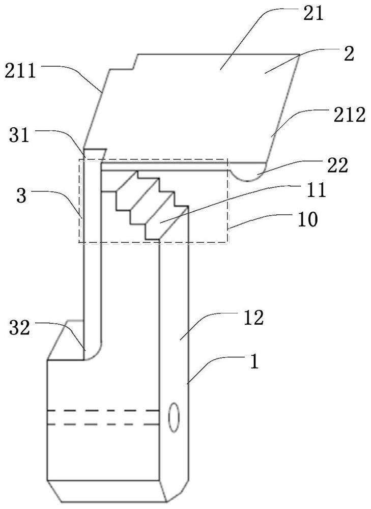
[0008] The present invention provides a substrate fixing device to solve the problems existing in the prior art that interference between the clamping part and the glass substrate is likely to occur in the process of magnetron sputtering, causing the glass substrate to break, and the number of times the clamping part is used is less and the use of Short-lived technical issues

Method used


Image

  • A substrate fixing device
  • A substrate fixing device
  • A substrate fixing device

Examples


Embodiment Construction

[0035] The preferred embodiments of the present invention are introduced below with reference to the accompanying drawings, in order to prove that the present invention can be implemented, and these embodiments can completely introduce the technical content of the present invention to those skilled in the art, so that the technical content of the present invention is more clear and easy to understand. However, the present invention can be embodied in many different forms of embodiments, and the protection scope of the present invention is not limited to the embodiments mentioned herein.

[0036] In describing the present invention, it is to be understood that the terms "central", "lateral", "upper", "lower", "left", "right", "vertical", "horizontal", "top", The orientation or positional relationship indicated by "bottom", "inner", "outer", etc. is based on the orientation or positional relationship shown in the drawings, and is only for the convenience of describing the presen...


PUM


Abstract

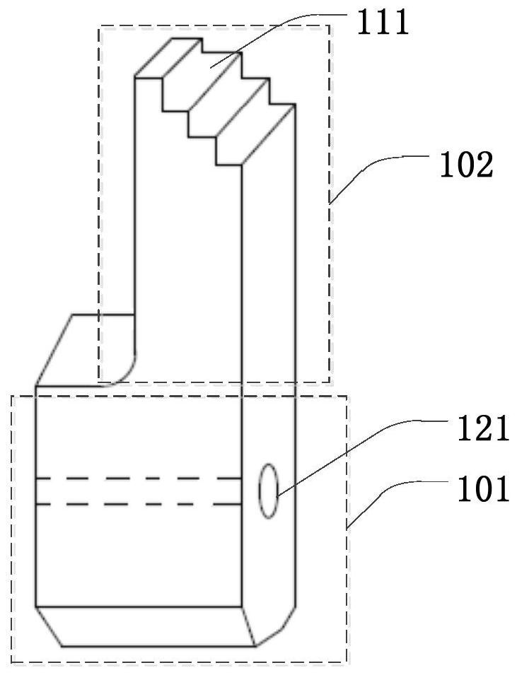
The present invention provides a substrate fixing device, which includes two opposite clamping parts, each clamping part includes a column, a first plate and a second plate; the top of the column is provided with a stepped part; the first A plate is located above the column, and its bottom surface is opposite to the stepped part; one end of the second plate is connected to the column, and the other end is connected to the first plate; the invention provides a substrate fixing device, the step part and the first plate and the second plate form a buffer zone, the buffer zone can provide more attachment space for the plasma, not only can prevent the phenomenon of interference between the glass substrate and the clamping part, but also can lift the glass substrate The yield rate; and can also increase the number of times of use of the clamping part, prolong the service life of the clamping part, and improve the stability of the operation of the substrate fixing device.

Description

technical field [0001] The invention relates to the field of display technology, in particular to a substrate fixing device. Background technique [0002] In the semiconductor display industry, magnetron sputtering technology is one of the important technologies in the display panel manufacturing process. Magnetron sputtering is a kind of physical vapor deposition. Its working principle is mainly to use Ar gas to ionize Ar ions under the action of high-voltage discharge. Ar ions bombard the target under the action of electromagnetic field to generate plasma. It is evenly deposited on the glass substrate to form the required film layer. The film layer formed by magnetron sputtering technology is relatively dense and uniform, and has a strong bonding force with the glass substrate. Magnetron sputtering is a common film-forming process in the OLED manufacturing process, for example, it is used to form metal films or organic films. [0003] In the film forming process of vert...

Claims


Application Information

Patent Timeline
Patent Type & Authority Patents(China)
IPC IPC(8): C23C14/50C23C14/35
CPCC23C14/35C23C14/50
Inventor 刘学
Owner WUHAN CHINA STAR OPTOELECTRONICS TECH CO LTD
Why Eureka
Try Eureka