
Dynamic calibration system for rocket engine thrust measuring device

A rocket engine and measuring device technology, applied in measuring devices, force/torque/power measuring instrument calibration/testing, instruments, etc., can solve problems such as the complexity of the rocket engine’s working process and the inability to strictly determine the relationship between the performance parameters of the engine , to achieve the effect of simple structure and convenient realization

Inactive Publication Date: 2019-07-26
BEIJING INST OF AEROSPACE TESTING TECH
View PDF7 Cites 0 Cited by
  • Summary
  • Abstract
  • Description
  • Claims
  • Application Information

AI Technical Summary

Problems solved by technology

[0003] The working process of the rocket engine is relatively complicated. In theoretical research, it is impossible to describe this process clearly by analyzing and calculating alone, and it is also impossible to strictly determine the quantitative relationship between the various performance parameters of the engine.

Method used


Image

  • Dynamic calibration system for rocket engine thrust measuring device

Examples


Embodiment Construction

[0019] The present invention will be described in further detail below in conjunction with the accompanying drawings and specific embodiments.

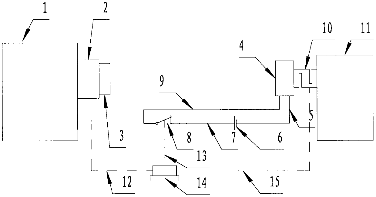
[0020] attached by figure 1 Given, the present invention is a dynamic calibration system for a rocket engine thrust measuring device, comprising a fixed frame (1), a working force sensor (2), a magnet (3), a coil (4), a wire 1 (5), a power supply (6 ), wire 2 (7), high-speed relay switch (8), wire 3 (9), standard force sensor (10), calibration bracket (11), measurement cable 1 (12), control cable (13), computer ( 14), measurement cable 2 (15).

[0021] The working force sensor (2) is installed on the fixed frame (1), the magnet (3) is connected with the working force sensor (2), the coil (4) and the magnet (3) are arranged on the same horizontal line, the coil (4) and the power supply (6) Connect with wire 1 (5), power supply (6) is connected with high-speed relay switch (8) with wire 2 (7), high-speed relay switch (8) is connected ...


PUM


Abstract

The invention discloses a dynamic calibration system for a rocket engine thrust measuring device. The system comprises a fixed frame, a working force sensor, a magnet, a coil, a wire 1, a power supply, a wire 2, a high speed relay switch, a wire 3, a standard force sensor, a calibration bracket, a measuring cable 1, a control cable, a computer and a measuring cable 2. The high-speed relay switch is normally closed, mutually repulsive magnetic fields are formed between the coil and the magnet after being electrified, and the forces received by the working force sensor and the standard force sensor are equal in magnitude and opposite in direction. After the computer issues a disconnect command, the high-speed relay switch is driven to disconnect by the control cable, the electromagnetic field in the coil disappears, the interaction force between the coil and the magnet disappears, and the forces on the working force sensor and the standard force sensor disappear at the same time, therebyrealizing rapid unloading of the standard force and producing a negative step dynamic force. The dynamic calibration is achieved by measuring the negative step signal of the working force sensor andcomparing the signal with the value of the standard force sensor.

Description

technical field [0001] The invention relates to a calibration system for a thrust measuring device of a rocket engine, in particular to a dynamic calibration system for a thrust measuring device of a rocket engine, which is suitable for dynamic calibration of the thrust measuring device of a rocket engine. Background technique [0002] Pre-research, design, production, and test are the four basic links in the development of any new type of rocket engine. Among them, the test work is extremely important, and some engine experts even think that the rocket engine is not the result of research, but the crystallization of experiments. This is mainly because almost all problems encountered in the process of developing the engine are solved by experiments. [0003] The working process of the rocket engine is relatively complicated. In theoretical research, it is impossible to describe this process clearly by analysis and calculation alone, and it is also impossible to strictly det...

Claims


Application Information

Patent Timeline
Patent Type & Authority Applications(China)
IPC IPC(8): G01L25/00
CPCG01L25/00
Inventor 刘万龙郑鑫朱昊伟曲胜邵帅马军强张奎好梁怀喜田国华胡旭坤李斌
Owner BEIJING INST OF AEROSPACE TESTING TECH
Learn More