
Crankshaft fatigue limit load prediction method based on improved stress field intensity method

A fatigue limit and prediction method technology, applied in special data processing applications, instruments, electrical digital data processing, etc., can solve problems such as poor accuracy and prediction result errors, and achieve the effect of reducing the impact of accuracy and wide engineering practical value

Active Publication Date: 2019-07-26
重庆达望曲轴机械制造有限公司
View PDF2 Cites 9 Cited by
  • Summary
  • Abstract
  • Description
  • Claims
  • Application Information

AI Technical Summary

Problems solved by technology

Among them, some scholars have proposed crack simulation technology, which predicts the fatigue limit load of three-dimensional solid components by constructing a standard crack body consistent with the stress gradient of the component. However, due to the essential difference in the stress state between the two, the prediction results sometimes lead to large error
[0004]In the previous research, the author used the stress field strength method to predict the fatigue limit load of the crankshaft with the same material properties and different structures. The research results show that the method is effective in predicting the fillet The fatigue limit load of crankshafts with the same radius has high accuracy, but the accuracy is poor when predicting crankshafts with different fillet radii, and the error is generally more than 10%.

Method used


Image

  • Crankshaft fatigue limit load prediction method based on improved stress field intensity method
  • Crankshaft fatigue limit load prediction method based on improved stress field intensity method
  • Crankshaft fatigue limit load prediction method based on improved stress field intensity method

Examples


Embodiment Construction

[0039] Below in conjunction with accompanying drawing of description, the present invention will be further described.

[0040] The invention provides a crankshaft fatigue limit load prediction method based on the improved stress field strength method, comprising the following steps:

[0041] 1) Select two crankshafts of the same material and different structures, and obtain the fatigue strength of the crankshaft itself as σ b ; Among them, the two crankshafts are the first crankshaft and the second crankshaft respectively, the fatigue limit load of the first crankshaft is known, and the fatigue limit load of the second crankshaft is unknown.

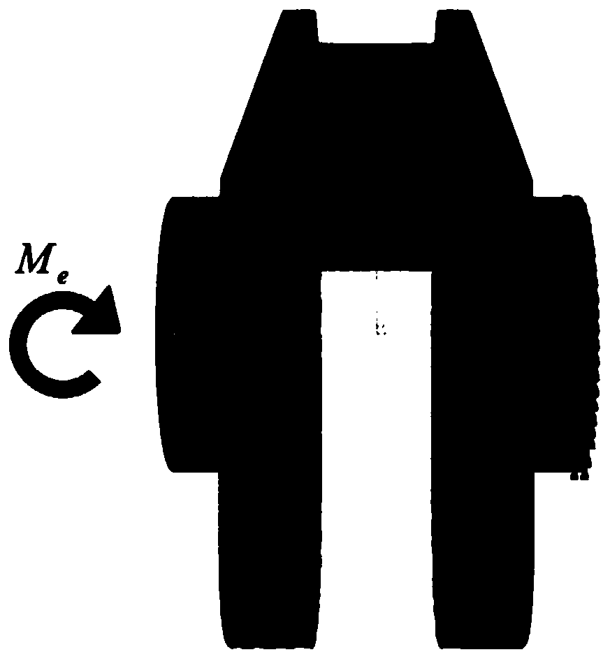
[0042] Such as figure 1 As shown, the two selected crankshafts are single-throw finite element model crankshafts. The first crankshaft is recorded as the No.0 crankshaft, and the second crankshaft is recorded as the No.1 crankshaft. The fatigue strength value of the crankshaft itself is 502MPa. i.e. σ b =502MPa.

[0043] 2) Analyze ...


PUM


Abstract

The invention discloses a crankshaft fatigue limit load prediction method based on an improved stress field intensity method, and the method comprises the steps: taking two crankshafts with the same material and different structures, wherein the fatigue limit load of a first crankshaft is known, and the fatigue limit load of a second crankshaft is unknown; analyzing the stress state of the first crankshaft under the action of the fatigue limit load, acquiring the stress distribution of the first crankshaft under the action of the limit load, and calculating the weight function of the first crankshaft, thereby determining the field diameter value of the first crankshaft; applying1000 N.m bending moment load to the second crankshaft, and obtaining the field diameter value of the second crankshaft and the field intensity value under the action of the bending moment load through relative stress gradient correction; and predicting the fatigue limit load of the second crankshaft. According to the method, the fatigue limit loads of crankshafts of the same material and different structures can be predicted more accurately, and the influence of the fillet radius of the crankshafts on the prediction result can be greatly reduced.

Description

technical field [0001] The invention relates to the technical field of prediction of crankshaft fatigue limit load, in particular to a crankshaft fatigue limit load prediction method based on an improved stress field strength method. Background technique [0002] Crankshaft and other engine parts will be impacted by various non-proportional loads during the working process, and some sudden changes in cross-section such as oil holes and rounded corners will cause stress concentration, which is often the source of fatigue failure. In response to this phenomenon, some scholars at home and abroad have done a lot of work in recent years. At present, in actual engineering, the acquisition of the fatigue characteristics of such parts mainly relies on two methods: test method and numerical simulation method. The former can usually accurately obtain the fatigue characteristics of parts, but often requires high cost and cannot be completed in the design stage of parts; the latter pre...

Claims


Application Information

Patent Timeline
IPC IPC(8): G06F17/50
CPCG06F2119/04G06F30/20G06F30/17G06F2119/06
Inventor 孙嵩松万茂松徐晓美张营孙宁
Owner 重庆达望曲轴机械制造有限公司
Learn More