Check patentability & draft patents in minutes with Patsnap Eureka AI!

Joining structure and joining method

一种接合方法、构造体的技术,应用在化学仪器和方法、焊接/焊接/切割物品、导体等方向,能够解决龟裂、工件破坏等问题

Active Publication Date: 2022-02-22
PANASONIC INTPROP MANAGEMENT CO LTD
View PDF7 Cites 0 Cited by
  • Summary
  • Abstract
  • Description
  • Claims
  • Application Information

AI Technical Summary

Problems solved by technology

In addition, as in Patent Document 2, even if the bottom surface between the projections of the contact surface of the anvil is formed of a surface without corners, when the workpiece contacts the bottom surface between the projections, the workpiece is excited while the deformation of the workpiece is suppressed. Therefore, damage or cracks occur in the workpiece

Method used


Image

  • Joining structure and joining method
  • Joining structure and joining method
  • Joining structure and joining method

Examples


no. 1 Embodiment approach

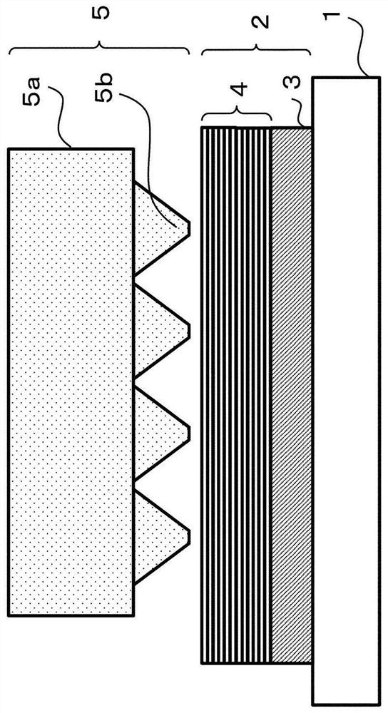
[0038] The joint structure according to the first embodiment is a joint structure in which a plurality of metals are laminated and joined. Between the flat portion, the front ends of the plurality of convex portions are made of curved surfaces. An example of this joint construct is set to Figure 4 The illustrated junction structure 7 is a laminated current collector plate 3 and electrode foil 4 . That is, as a plurality of metals, the electrode foil 4 and the collector plate 3 are exemplified. The electrode foil 4 is a laminate of a plurality of metal foils. The metal foil is copper foil. The collector plate 3 is a copper plate. In this case, for example, the collector plate 3 constitutes a copper wire in the lithium secondary battery, and the electrode foil 4 constitutes a negative electrode. However, the present disclosure is not limited to the current collector plate 3 or the electrode foil 4 , as long as it is a metal that can be ultrasonically bonded. The current c...

no. 2 Embodiment approach

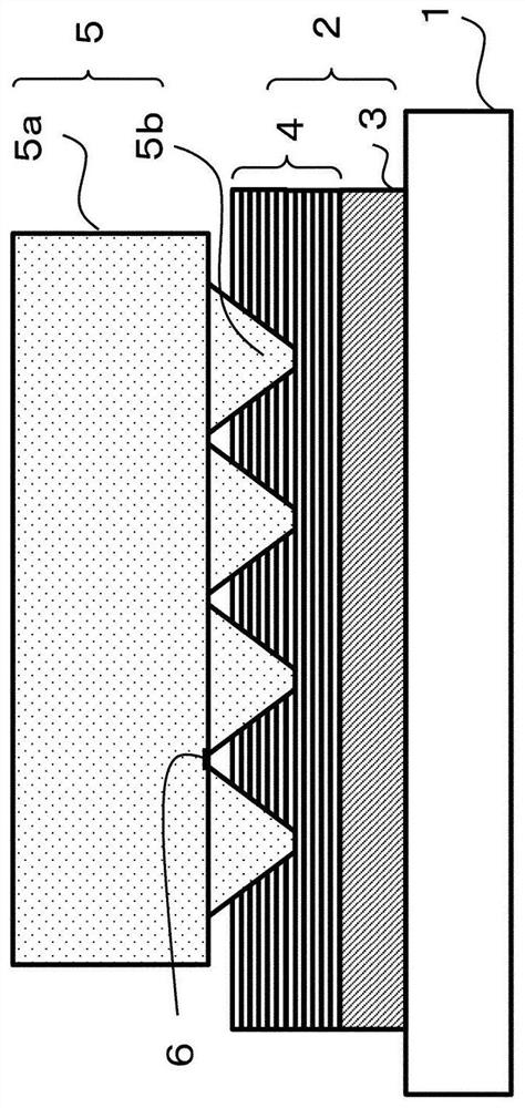
[0060] Image 6 It is a schematic sectional view which shows the preparation process of the ultrasonic bonding in 2nd Embodiment. In addition, matters not described are the same as those of the first embodiment. The difference from the first embodiment is that the section parallel to the main surface of the anvil 5 ( Image 6 The cross-sectional area of ​​the protrusion bottom surface 10 at the cross-section in the depth direction) is not uniform.

[0061] In the bonding step, the electrode foil 4 straddles between adjacent protrusions 5 b and spreads to the peripheral portion of the anvil 5 . The electrode foil 4 spreading from the center portion of the anvil 5 to the peripheral portion flows between the protrusions 5 b located at the peripheral portion of the anvil 5 . Furthermore, the electrode foil 4 located outside the anvil 5 also flows into between the protrusions 5 b located in the peripheral portion of the anvil 5 . Therefore, more electrode foil 4 flows between t...


PUM


Abstract

The present invention provides a joined structure in which metals are joined to each other, and a joining method in which peeling of the joined portion is suppressed, thereby achieving high reliability. The joint structure according to the present disclosure is a joint structure in which a plurality of metals are laminated and joined, the plurality of metals having a plurality of convex portions arranged on a surface located in the lamination direction, and a plurality of protrusions arranged on the plurality of The flat portion between the convex portions, and the front ends of the plurality of convex portions are formed of curved surfaces.

Description

technical field [0001] The present invention relates to a joining structure and a joining method of metals. Background technique [0002] Ultrasonic bonding is known as one of methods for bonding metals together. Ultrasonic bonding is a method in which stacked workpieces are placed on an anvil (fixed end), pressed by an anvil (excitation source) and ultrasonically vibrated to form a bonded structure by joining the workpieces. At this time, the thickness of the portion of the workpiece that is in contact with the abutting surface of the anvil decreases. In addition, among the workpieces, stress concentrates at the portion where the bottom surface between the protrusions formed on the abutting surface of the anvil contacts. Therefore, the workpieces in these parts tend to be damaged or cracked. Such local breakage or cracks may cause detachment of the joint portion during actual use or assembly work of the joint structure, and may adversely affect product reliability. [0...

Claims


Application Information

Patent Timeline
Patent Type & Authority Patents(China)
IPC IPC(8): B23K20/10H01M4/02H01M4/13
CPCB23K20/10B32B15/01B23K20/106B23K2103/166B23K2101/38H01M4/043H01M4/1395Y02E60/10B29C65/081B29L2031/3468B29C66/21B29C66/43B29C66/81433B32B3/02H01M4/13H01M4/02B29L2009/003
Inventor 广濑贵之谷口泰士熊泽诚二芦田高之
Owner PANASONIC INTPROP MANAGEMENT CO LTD
Features
  • R&D
  • Intellectual Property
  • Life Sciences
  • Materials
  • Tech Scout
  • Unparalleled Data Quality
  • Higher Quality Content
  • 60% Fewer Hallucinations
Learn More