
Bridge comparative switch cabinet phase checking device

A switch cabinet, nuclear phase technology, applied in the measurement device, the phase angle between voltage and current, and the measurement of electrical variables, etc., can solve the problems of inaccurate test results, deviation of collected signals, and many electromagnetic interference signals. The effect of saving manpower, effective electricity inspection, safe and simple operation

Inactive Publication Date: 2019-07-30
CHINA DATANG CORP SCI & TECH RES INST CO LTD EAST CHINA BRANCH +1
View PDF9 Cites 0 Cited by
  • Summary
  • Abstract
  • Description
  • Claims
  • Application Information

AI Technical Summary

Problems solved by technology

The wireless phase verification device is mostly used for phase verification of high-voltage lines. When it is used for phase verification of switch cabinets, there are the following problems: due to the small space in the switch cabinet and the presence of closed isolation baffles, it is very troublesome to open the closed isolation baffle when collecting , because the three-phase bus in the switchgear is very close and there are many electromagnetic interference signals in the switchgear, there may be deviations when collecting signals, and the test results are inaccurate

Method used


Image

  • Bridge comparative switch cabinet phase checking device
  • Bridge comparative switch cabinet phase checking device
  • Bridge comparative switch cabinet phase checking device

Examples


Embodiment Construction

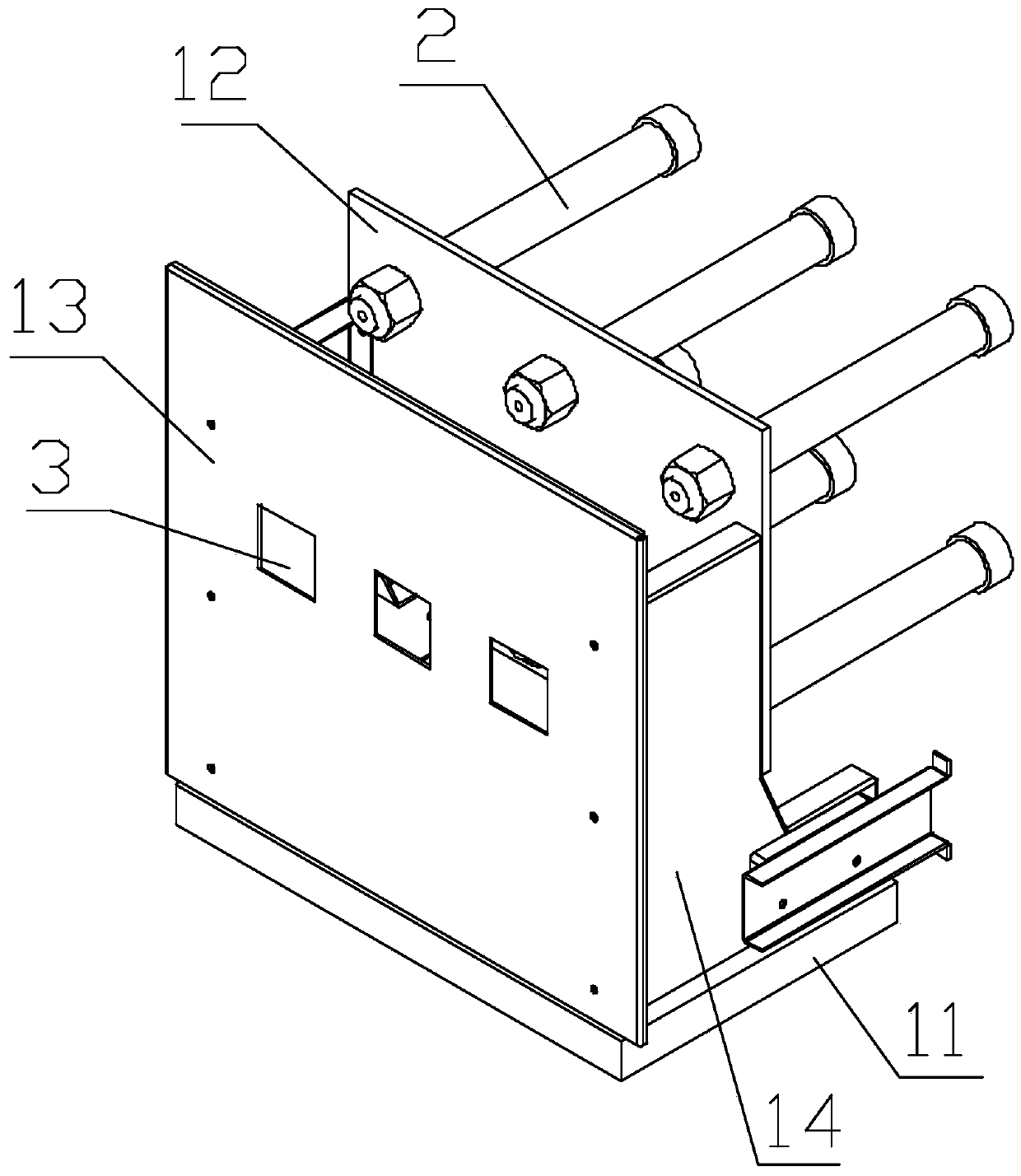
[0026] refer to figure 1 , a bridge comparison switch cabinet nuclear phase device proposed by the present invention, including: frame, six resistance arms 2 and three potentiometers 3.

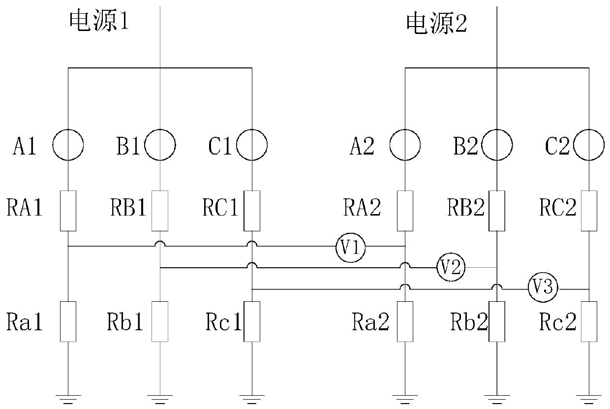
[0027] The six resistance arms 2 are all installed on the vehicle frame, and the six resistance arms 2 correspond to the three phases A, B, and C of the first power supply and the second power supply to be checked respectively. Each resistance arm 2 is composed of a measuring resistor and a voltage dividing resistor connected in series, and the voltage dividing resistor is smaller than the measuring resistor. The resistor arm 2 is connected to the corresponding power supply phase through the measuring resistor, and grounded through the voltage dividing resistor, and the connection point between the measuring resistor and the voltage dividing resistor is used as the core phase voltage output terminal.

[0028] Two resistance arms 2 corresponding to the same phase of the first power supply and...


PUM


Abstract

The invention provides a bridge comparative switch cabinet phase checking device, which comprises a vehicle frame, six resistive arms and three potentiometers. The six resistive arms are all mounted on the vehicle frame and correspond to phases A, phases B and phases C of a first power supply and a second power supply to be subjected to phase checking correspondingly; each resistive arm is constituted by a measuring resistor and a divider resistor which are connected in series, wherein the divider resistor is smaller than the measuring resistor in resistance, and the connecting joints of the measuring resistors and the divider resistors serve as the phase checking voltage output ends; every two resistive arms corresponding to the same phase of the first power supply and the second power supply constitute a pair of comparative arms; and the three potentiometers and the three pairs of comparative arms correspond one to one, and the two input ends of each potentiometer are connected withthe phase checking voltage output ends of the two resistive arms in the corresponding comparative arms correspondingly. According to the bridge comparative switch cabinet phase checking device, the resistive arms and the potentiometers are both mounted on the vehicle frame, a phase checking test can be carried out only by pushing the vehicle frame into a switch cabinet, operation is safe and easy,the safety risk is lowered greatly, and manpower is saved greatly.

Description

technical field [0001] The invention relates to the technical field of electrical equipment test and detection, in particular to a bridge comparison type switch cabinet phase verification device. Background technique [0002] With the development of my country's economy, both enterprises and residential users have more stringent requirements for power quality and power supply reliability. The "hand in hand" ring network power supply mode is the best way to improve power supply reliability. direct and effective way. In the operation of ring network power supply, the outstanding problem is that when the phase sequence and phase of the two power supplies are inconsistent and parallel operation is performed, it will cause a short circuit between phases, resulting in personal casualties and damage to grid equipment. Therefore, new substations and transmission lines after new construction, reconstruction and expansion, and before the line is overhauled and delivered to users, must...

Claims


Application Information

Patent Timeline
IPC IPC(8): G01R25/00
CPCG01R25/005
Inventor 张树铭盛明珺赵淼张伟吴影李飞
Owner CHINA DATANG CORP SCI & TECH RES INST CO LTD EAST CHINA BRANCH
Learn More