Wing-shaped optical fiber core adjustment structure

A core-tuning and optical fiber technology, applied in the field of X/Y-axis core-alignment alignment, can solve problems such as increasing the number of structural parts, material costs and processing costs, limited space for core-alignment structures, and occupying space for core-alignment optical fibers, etc., to achieve Avoid the decline in the quality of optical fiber fusion, ensure the quality of core alignment, and reduce the occupied space

Pending Publication Date: 2019-07-30
李亮
View PDF7 Cites 3 Cited by
  • Summary
  • Abstract
  • Description
  • Claims
  • Application Information

AI Technical Summary

Problems solved by technology

[0006] There are many types of optical fiber alignment structures currently designed. The common point is that the alignment part and the imaging part are respectively installed on the same fixed base. Although the optical fiber alignment of the core part cooperates with each other, they all move relative to the fixed base, that is, the transmission structure of the optical fiber alignment operation and the transmission structure of the lens (or CCD module) of the imaging part operate separately. They are not related to each other, just like hands and eyes. Although they can handle the same object, they are both responsible for the brain. The eyes do not grow on the hands. The disadvantages of this are:
[0007] 1. When the core-aligning structure performs the core-aligning action, the optical fiber moves with respect to the microscope lens fixed on the base, which will change the imaging focal length, cause the image to be out of focus, affect the imaging quality and even affect the alignment quality
[0008] 2. The core-adjusting structure is designed with the base as the support point. Due to the influence of the space occupied by the installation of two 90-degree included angle microscope lenses (the distance between the objective lens of the microscope lens and the optical fiber of the observed object is about 10 mm, and the diameter of the lens itself is greater than 10 mm), it can be used The space used by the centering structure is very limited. It is necessary to place a V-shaped groove, two electrodes and their connection lines, and a support body supporting the V-shaped groove in this space to realize the micro-adjustment operation. Higher requirements are put forward, and the number of structural parts, material costs, and processing costs are also increased in practice.
[0009] 3. Based on the first and second explanations, the existing design occupies most of the space around the core-tunable fiber, and the scalability of the structure is not strong, which hinders other functional modules that need to be added to new applications: for example, to achieve fusion splicing Spot monitoring in the process requires the installation of a spot detector, a third-angle lens and a CCD imaging plate for new fiber alignment to achieve vertical observation of the fiber end face, non-electrode heating devices that need to be added to achieve tapering operations, etc. Modules often require space within the angle between the two lenses of the existing design, and these spaces are occupied by the alignment structure

Method used


Image

  • Wing-shaped optical fiber core adjustment structure
  • Wing-shaped optical fiber core adjustment structure
  • Wing-shaped optical fiber core adjustment structure

Examples


Embodiment Construction

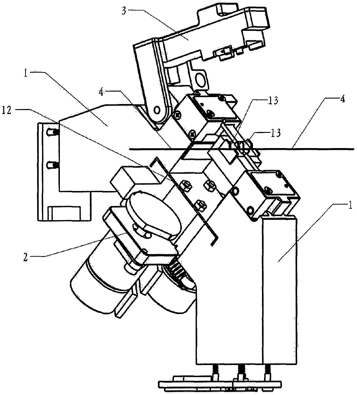
[0065] figure 1 It is the front view of the core structure of the airfoil fiber. As shown in the figure: two 1. main body components are connected as a whole through 12. connecting reeds. 2. The cam adjustment assembly is installed in the middle of 12. The connecting reed. 3. The hammer assembly is pivotally connected to the upper part of a 1. main body assembly, and can be opened and closed. The state shown in the figure is the open state. 4. The optical fiber is placed on the 13. V-groove of the two 1. body assemblies.

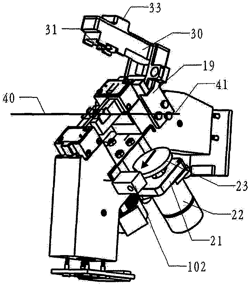
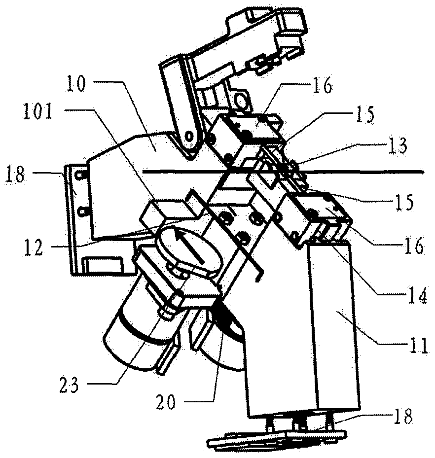
[0066] Figure 2A / Figure 2B It is the left and right side structure diagram of the airfoil fiber core adjustment structure. Yes figure 1 Further detailed structure diagram, as shown in the figure: take 12. connecting spring as the boundary, one side is 10. left assembly, 13. V-shaped groove, 14. V-shaped groove support frame, 15. electrode, 16. electrode fixing Board and connecting line, 18. CCD imaging board, 19. pressure hammer stopper, directly ...


PUM


Abstract

The invention provides a wing-shaped optical fiber core adjustment structure. The structure comprises main body assemblies, a cam adjustment assembly, and a pressing hammer assembly, wherein a lens, acore adjustment V-shaped groove and a discharge electrode of each main body assembly participate in optical fiber core adjustment as a whole; and during operation, optical fiber imaging distances anddistances between optical fibers and the electrodes remain unchanged, and core adjustment pivots and force output points can be flexibly arranged. The wing-shaped optical fiber core adjustment structure provided by the invention has the advantages that the space occupation ratio of the core adjustment structure is reduced, so that a basic platform can be provided for the installation of other function control modules for special optical fiber splicing, fiber Bragg grating sensor manufacturing, optical fiber tapering, end cap splicing, vertical imaging of end surfaces of spliced optical fibers, polarization-maintaining optical fiber splicing, photonic crystal optical fiber splicing, non-electrode heating splicing, and the like; compared with the conventional design, the core adjustment structure achieves higher simplicity in structure, a higher core adjustment resolution, higher reliability, lower structure cost and lower processing requirements; and the core adjustment structure can be further applied for X/Y-axis core adjustment of the conventional optical fiber fusion splicer.

Description

technical field [0001] The invention relates to an optical fiber core adjustment structure, which is a precision instrument, in particular to an optical fiber core adjustment structure with an optical fiber microscope head, an image sensor, a V-groove for placing and holding the optical fiber, and a discharge electrode. The core adjustment of the optical fiber aimed at by the present invention is that the plane of the end face of the optical fiber is aligned with the core, and does not involve the pushing of the left and right optical fibers. In a general sense, the plane alignment of the optical fiber is called X / Y-axis alignment, and the movement of the left and right optical fibers is the Z-axis alignment. The present invention relates to the X / Y-axis alignment. [0002] technical background [0003] Optical fiber fusion splicer is a kind of splicing equipment that uses the high temperature formed by a pair of electrodes to discharge arcs to melt the end faces of the two-c...

Claims


Application Information

Patent Timeline
Patent Type & Authority Applications(China)
IPC IPC(8): G02B6/255
CPCG02B6/2555
Inventor 李亮
Owner 李亮
Why Eureka
Try Eureka