Corrosion protection for air-cooled condensers

An air-cooled, corrosion-protected technology used in steam/vapor condensers, instrumentation, damage protection, etc. to solve problems such as reduced heat transfer efficiency, equipment downtime, and reduced product output

Inactive Publication Date: 2019-07-30
GENERAL ELECTRIC CO
View PDF9 Cites 0 Cited by
  • Summary
  • Abstract
  • Description
  • Claims
  • Application Information

AI Technical Summary

Problems solved by technology

[0007] The effects of problems associated with corrosion damage in air-cooled condensers include increased operating and maintenance costs due to tube failure, more frequent shutdowns for cleaning and repairs, reduced heat transfer efficiency, and possible product Reduced production or even equipment downtime

Method used


Image

  • Corrosion protection for air-cooled condensers
  • Corrosion protection for air-cooled condensers

Examples


Embodiment Construction

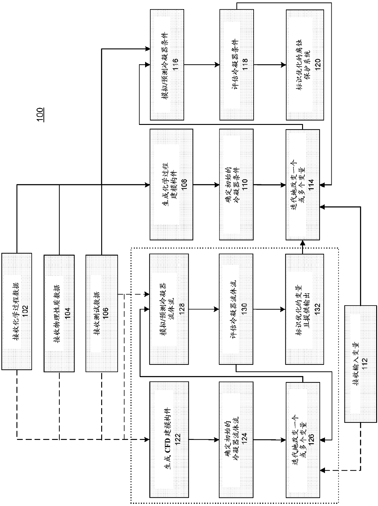
[0016] A method for developing an optimized corrosion protection system for air-cooled condensers is disclosed. The generated model was used to optimize the treatment and supply of corrosion inhibitors to the vapor system of an air-cooled condenser in order to inhibit and minimize corrosion. In general, a corrosion inhibitor is any substance that effectively reduces the rate of corrosion when added to the environment. Inhibitors can be identified with respect to their function (eg, removal of corrosive species, passivation, precipitation, or adsorption). The solution optimizes, for example, the chemistry of corrosion protection feed, timing, feed rate and feed point.

[0017] In an embodiment, a computer-implemented method for establishing a corrosion protection system for an air-cooled condenser utilizes one or more processors and associated memory storing one or more programs executed, the one or more programs including instructions for: receiving data associated with at l...


PUM


Abstract

A method for establishing a corrosion protection system for an air cooled condenser is disclosed. The method includes receiving data associated with the physical properties and chemical process conditions of the air cooled condenser, utilizing a chemical process modeling component to simulate conditions of the air cooled condenser, and identifying an optimized corrosion protection system based onan evaluation of iteratively altered input variables.

Description

technical field [0001] The present invention relates to a method for inhibiting corrosion caused by process conditions in air-cooled condensers. Background technique [0002] In steam generating systems such as power plants, air-cooled condensers are used to convert steam from a gas to a liquid after the steam has passed through a steam turbine. One widely used dry cooling system is direct dry cooling. In this dry cooling method, water vapor expands in a steam turbine, exits from the turbine through a relatively large diameter steam tube, and then passes through an upper distribution chamber where the water vapor enters the steam-air heat exchange condensers, such as air-cooled condensers. [0003] Air cooled condensers may include steam inlet piping, condenser tubes and condensate outlet piping. Turbine exhaust steam enters the condenser through the steam inlet pipe and flows through the condenser tubes. The steam condenses inside the condenser tubes, which are cooled e...

Claims


Application Information

Patent Timeline
Patent Type & Authority Applications(China)
IPC IPC(8): F28F27/00F28B11/00G06F17/00
CPCF28F27/00F28B11/00F28F2200/00F28F19/00G06F30/20G06F2111/10G06F30/28
Inventor T.J.戴尔A.M.罗西R.特罗斯巴赫G.J.罗宾逊
Owner GENERAL ELECTRIC CO
Why Eureka
Try Eureka