Special-shaped key groove high-speed machining platform and machining method thereof

A technology for processing platforms and special-shaped keys, used in metal processing equipment, planers, manufacturing tools, etc., can solve the problems of easy occurrence of stress cracking, low processing dimensional accuracy, long time consumption, etc., to achieve good product specification adaptability, reduce effect of time

Pending Publication Date: 2019-08-02
ZHENJIANG ZHENGKAI ELECTRONICS
View PDF0 Cites 0 Cited by
  • Summary
  • Abstract
  • Description
  • Claims
  • Application Information

AI Technical Summary

Problems solved by technology

Among them, the material heating extrusion method is used to realize the processing of the keyway, which has the advantage of low processing cost for a single product, but at the same time it has the disadvantages that the material is heated at high temperature, prone to stress cracking, and there is an oxide layer on the surface of the material. At the same time, its processing The dimensional accuracy is low, and it is difficult to realize the application in high-precision miniaturized products; the precision casting method is used to process the keyway, which has the advantage of high processing precision, but at the same time, the shape and size of the keyway of the product are determined by the mold. , can only be solved by continuously opening molds, the cost is extremely high, and the adaptability is relatively narrow; while using the linear motion of the machine tool guide rail to process the keyway with the gear shaping method has the advantage of high product processing accuracy, but at the same time using the axis of the machine tool linear guide rail The gear-shaping tool is driven by the translation to realize the shoveling and inserting process of the product, which limits the processing speed of the product, resulting in low processing efficiency. A keyway requires at least 20-30 processing actions to realize, which takes a long time

Method used


Image

  • Special-shaped key groove high-speed machining platform and machining method thereof
  • Special-shaped key groove high-speed machining platform and machining method thereof
  • Special-shaped key groove high-speed machining platform and machining method thereof

Examples


Embodiment Construction

[0031] The present invention is described in further detail now in conjunction with accompanying drawing. These drawings are all simplified schematic diagrams, which only illustrate the basic structure of the present invention in a schematic manner, so they only show the configurations related to the present invention.

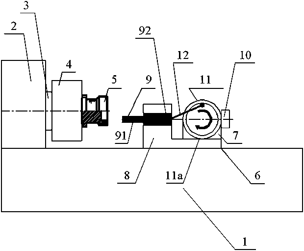
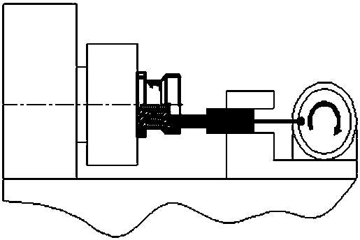
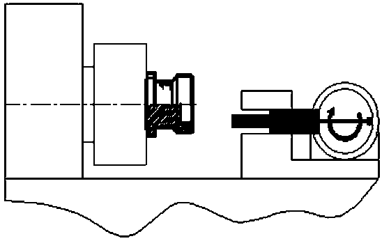
[0032] Such as Figure 1-3 As shown, a special-shaped keyway high-speed machining platform includes a machine tool 1, a machine tool support 2, a rotating drive shaft 3, a machine tool chuck 4, a workpiece to be processed 5, a machine tool moving guide rail 6, an eccentric wheel mounting frame 7, a tool carrying platform 8, Processing tool 9, driving motor 10, rotating eccentric wheel 11, and eccentric wheel connecting rod 12; wherein, machine tool support 2 is fixedly arranged on one side of machine tool 1 working surface, and machine tool is installed on machine tool support 2 through rotating drive shaft 3 Chuck 4, the workpiece 5 to be processed is instal...


PUM


Abstract

The invention relates to a special-shaped key groove high-speed machining platform and a machining method. The special-shaped key groove high-speed machining platform is characterized by comprising amachine tool (1), a machine tool support (2), a rotary driving shaft (3), a machine tool chuck (4), a to-be-machined workpiece (5), a machine tool moving guide rail (6), an eccentric wheel mounting frame (7), a tool bearing table (8), a machining tool (9), a driving motor (10), a rotary eccentric wheel (11) and an eccentric wheel connecting rod (12). An eccentric wheel guide rail reciprocating method is adopted, the limitation on the moving speed of a machine tool screw rod is avoided, the speed is completely dependent on the running speed of the driving motor, and the rotating speed of 6000 revolutions or higher can be achieved; and, while ensuring the machining accuracy, machining a key groove can be realized only by reciprocating the machining tool back and forth, so that the machiningtime of the key groove is shortened.

Description

technical field [0001] The invention relates to a keyway processing platform and a processing method, in particular to a special-shaped keyway high-speed processing platform and a processing method. Background technique [0002] With the rapid development of the communication industry, the trend of product integration is becoming more and more obvious. It is required for the product to realize multiple transmission channels running inside a shell, and for the function of preventing mis-insertion when it is in the meshing state, and the radial positioning deviation of the meshing. Higher and higher. Common methods for machining keyways in the prior art include material heating extrusion, precision casting, and machine tool guide rail linear motion. Among them, the material heating extrusion method is used to realize the processing of the keyway, which has the advantage of low processing cost for a single product, but at the same time it has the disadvantages that the materia...

Claims


Application Information

Patent Timeline
Patent Type & Authority Applications(China)
IPC IPC(8): B23D3/02
CPCB23D3/02
Inventor 胡祥
Owner ZHENJIANG ZHENGKAI ELECTRONICS
Why Eureka
Try Eureka