Platform type machine tool bed

A platform type, machine tool technology, applied in the field of data machine tools, can solve the problems of poor lubrication effect on the top surface of tailstock guide rails and high tail guide rails, and achieve the effects of reducing friction, enhancing lubrication effect and prolonging service life.

Active Publication Date: 2019-08-02
CHONGQING HONGGANG CNC MACHINE TOOL
View PDF8 Cites 1 Cited by
  • Summary
  • Abstract
  • Description
  • Claims
  • Application Information

AI Technical Summary

Problems solved by technology

[0004] The present invention intends to provide a platform-type machine bed to solve the problem that the top surface of the tail rail is relatively high, and the flowing lubricating oil is difficult to flow through the top surface of the tail stock rail, resulting in poor lubrication effect on the top surface of the tail stock rail question

Method used


Image

  • Platform type machine tool bed
  • Platform type machine tool bed
  • Platform type machine tool bed

Examples


Embodiment 1

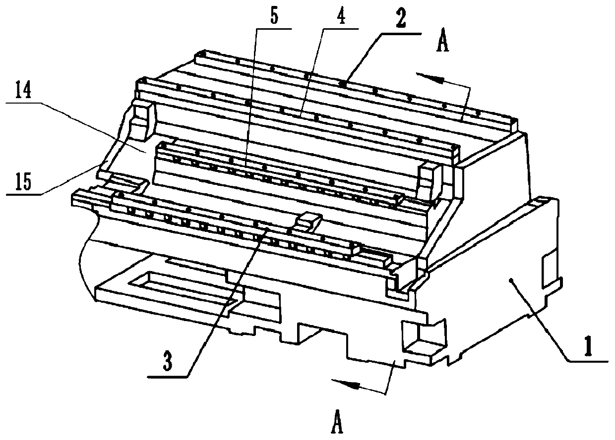
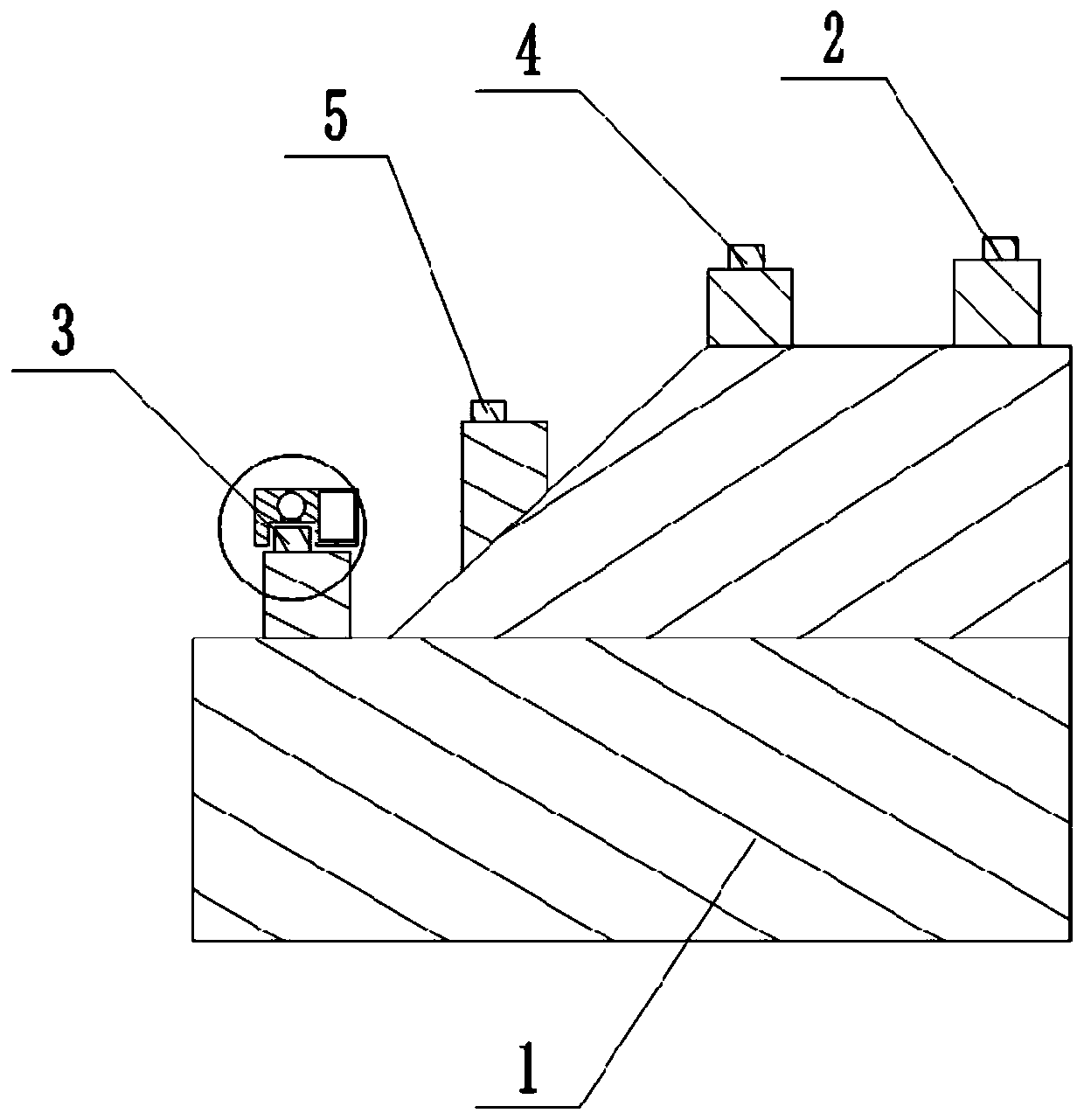
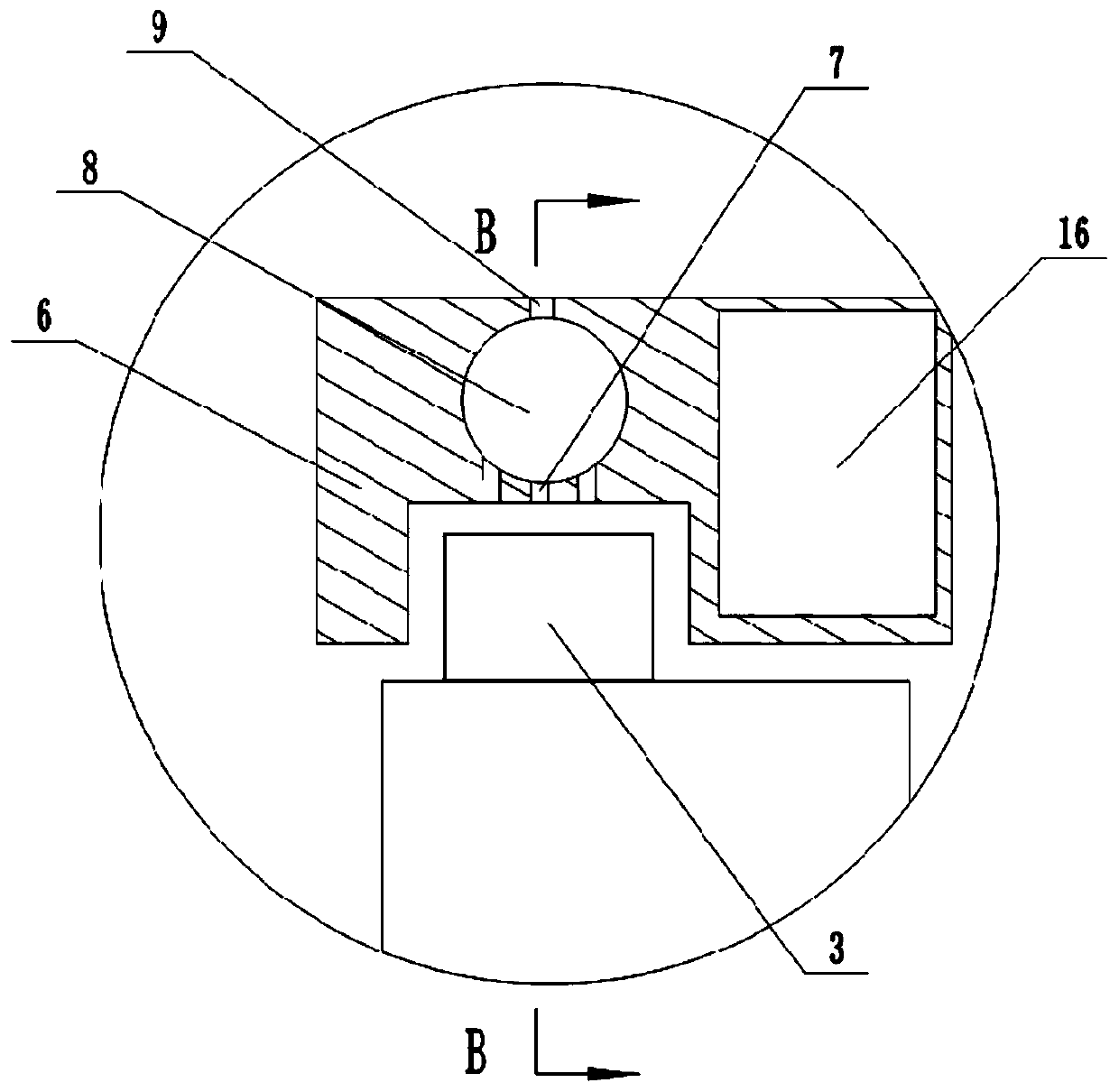
[0037] Basic as attached figure 1 , figure 2 Shown: a platform type machine bed, including a bed base 1 and a tailstock guide rail, the tailstock guide rail is fixedly installed on the top surface of the bed base 1 longitudinally (the length direction of the bed base 1), and the number of tailstock guide rails is two, For the convenience of description, the two tailstock rails are named the first tailstock rail 3 and the second tailstock rail 5 respectively. The first tailstock rail 3 and the second tailstock rail 5 are arranged horizontally in steps. The top surfaces of a tailstock guide rail 3 and a second tailstock guide rail 5 are both parallel to the positioning base surface at the bottom of the bed base 1, and a slider 6 is slidably connected to the first tailstock guide rail 3 and the second tailstock guide rail 5 to The slider 6 on the first tailstock guide rail 3 is taken as an example to illustrate the structure of the slider 6, such as image 3 , Figure 4 As shown, ...

Embodiment 2

[0044] Such as Image 6 , Figure 7 As shown, the difference between this embodiment and the first embodiment is that the driving mechanism includes a mounting portion 12 and a wiper 13 that are fixedly connected to each other by bolts. The wiper 13 is erected on the tailstock rail and attached to the tailstock rail. In the cleaning layer, the friction damping between the wiper 13 and the tailstock rail is greater than the friction damping between the slider 6 and the tailstock rail. Here, the slider 6 is made of stainless steel and the wiper 13 is made of rubber as an example; the free end of the piston rod 11 and the installation The part 12 is fixedly connected by bolts.

[0045] Such as Image 6 As shown, when in use, the tailstock assembly slides back and forth on the guide rail to drive the slider 6 to slide back and forth synchronously. When the sliding block 6 moves to the left, the wiper 13 moves to the right relative to the sliding block 6, thereby driving the piston 1...


PUM


Abstract

The invention relates to the technical field of data machine tools, in particular to a platform type machine tool bed. The platform type machine tool bed comprises a bed seat and tailstock guide rails, the tailstock guide rails are longitudinally and fixedly arranged on the top surface of the bed seat, the number of the tailstock guide rails is two, the two tailstock guide rails are transversely arranged in a stepped manner, and the top surfaces of the tailstock guide rails are parallel to a positioning base surface at the bottom of the bed seat; sliding blocks are slidably connected to the tailstock guide rails, through holes are formed in the sliding blocks, first one-way valves are arranged on the through holes, and the lower ends of the through holes are located on the top surfaces ofthe tailstock guide rails; negative pressure cavities are arranged in the sliding blocks, the negative pressure cavities communicate with the through holes, connecting ports are further formed in thenegative pressure cavities, and pressure valves are arranged on the connecting ports; and pistons are arranged in the negative pressure cavities in a sliding mode in the sliding direction of the sliding blocks, piston rods are hinged to the pistons, and driving mechanisms used for driving the pistons to slide are fixedly arranged on the piston rods. By adopting the scheme, the top surfaces of thetailstock guide rails can be lubricated, and the service lives of the tailstock guide rails are prolonged.

Description

Technical field [0001] The invention relates to the technical field of data machine tools, in particular to a platform type machine tool bed. Background technique [0002] The inclination angle of the guide rail of the machine tool with the inclined bed layout is usually 45°, 60° or 75°, which can not only improve the force under the same conditions, but also improve the rigidity of the bed through the overall closed section design, especially The arrangement with automatic tool changer is more convenient. Therefore, the machine tool with inclined bed layout is widely used in the machining industry, and is suitable for the multi-variety processing of various precision and complex rotating parts. [0003] In the existing machine tools with inclined bed layout, the top plane of the guide rail and the guide rail mounting surface are parallel, that is to say, the top surface of the guide rail and the positioning base surface at the bottom of the bed have an angle, resulting in the use...

Claims


Application Information

Patent Timeline
IPC IPC(8): B23Q1/01B23Q11/12B23Q11/00
CPCB23Q1/015B23Q1/017B23Q11/0042B23Q11/124
Inventor 汪传宏
Owner CHONGQING HONGGANG CNC MACHINE TOOL
Why Eureka
Try Eureka