
Patsnap Eureka
For R&D, Patsnap Eureka makes reading and utilizing patents & technical documents easy.
Patsnap Eureka AIR
Designed for self-driven R&D workflows. Generate viable solutions, solve complex R&D challenges, empower your innovation with AI.

Patsnap Eureka Materials
Designed for material experts only. Revolutionize your material R&D, from search, analyze, to developing new materials.

TechResearch
Generate reliable direction feasibility study reports for your R&D in just a few steps.

TechSeek
Discover and master advanced knowledge NOW. Basics, ideas, possibilities, all at once.

TechMind
As an expert in R&D Theories, TechMind can generates customized viable solutions instantly.

TechRisk
Analyze your overall solution with one click, know your potential R&D risks in advance.

TechMonitor
Get weekly tech updates, stay abreast of the latest tech innovations and key insights.
Magnetofluid hydraulic grinding wheel and controllable finishing processing method
A finishing process and magnetic fluid technology, applied in the direction of bonded grinding wheel, metal processing equipment, manufacturing tools, etc., can solve the problems of difficult adjustment of the size of the processing area, poor processing quality, low processing efficiency, etc., and achieve obvious magneto-rheological effect , improve the processing quality, good versatility
- Summary
- Abstract
- Description
- Claims
- Application Information
AI Technical Summary
Problems solved by technology
Method used
Image

Examples
Embodiment 1
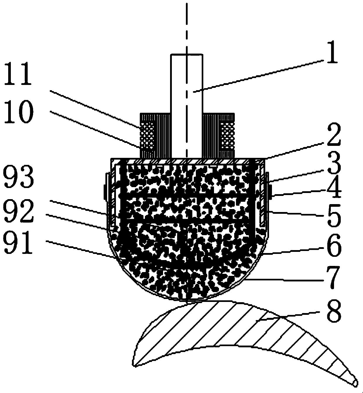
[0042] combine figure 1 , figure 2 , Image 6 , a magnetic fluid hydraulic grinding wheel, which is connected to the main shaft 1 of the machine tool, including a spherical crown grinding wheel 7, a grinding wheel base 3, and a magnetic field generating device;
[0043]The grinding wheel base 3 is connected to the main shaft 1, and the grinding wheel base 3 is provided with a magnetic field generating device and a spherical crown grinding wheel 7, and a magnetic fluid is sealed between the spherical crown grinding wheel 7 and the grinding wheel base 3, and the spherical crown grinding wheel 7 is a flexible rubber-based diamond Grinding wheel; a fastening ring 4 is also provided between the spherical crown grinding wheel 7 and the grinding wheel base 3 . Based on Pascal's law, after the magnetic fluid is squeezed by the workpiece 8, the internal static pressure will be transferred to the entire surface of the workpiece 8 in contact with the spherical crown grinding wheel 7, ...
Embodiment 2
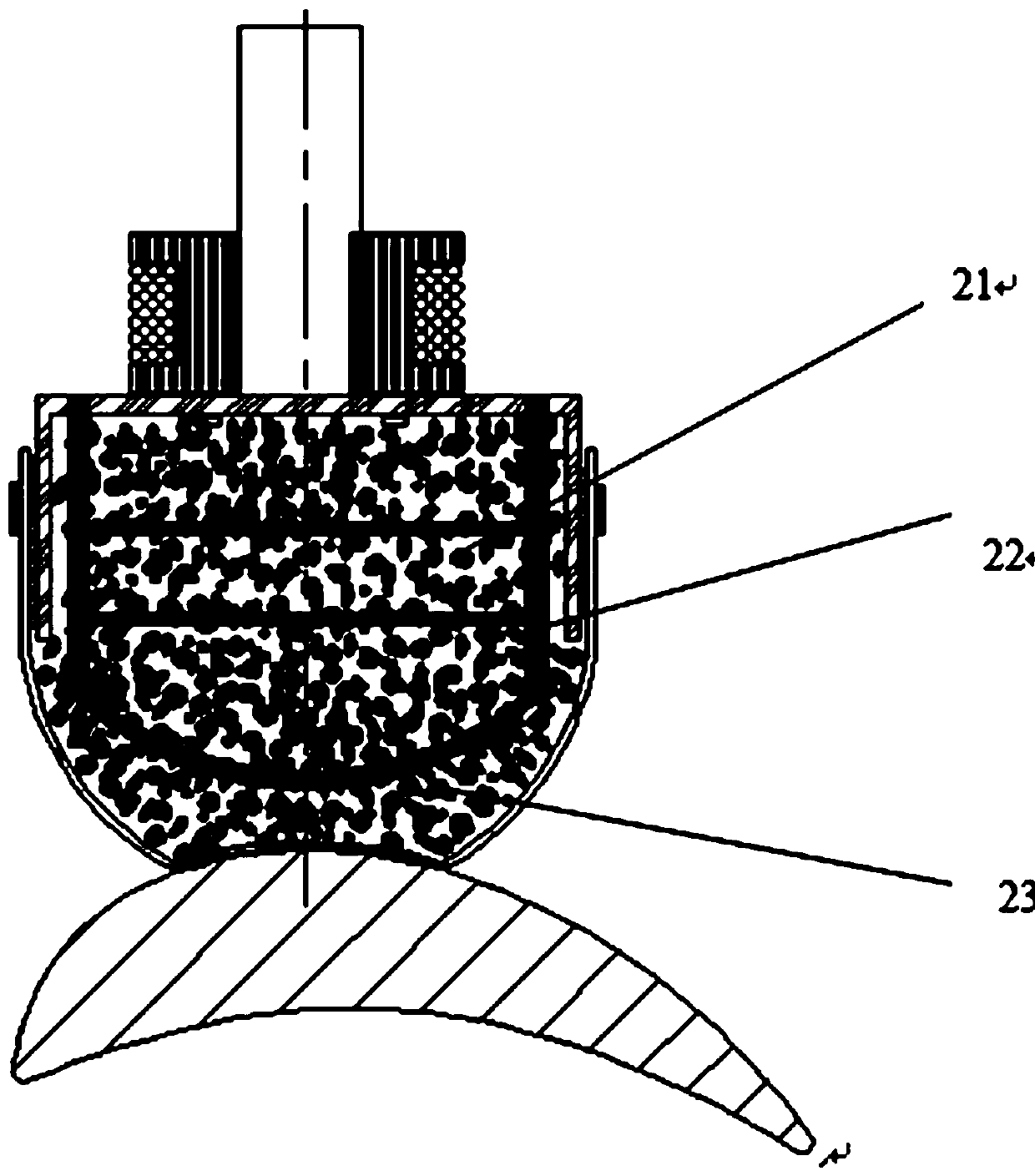
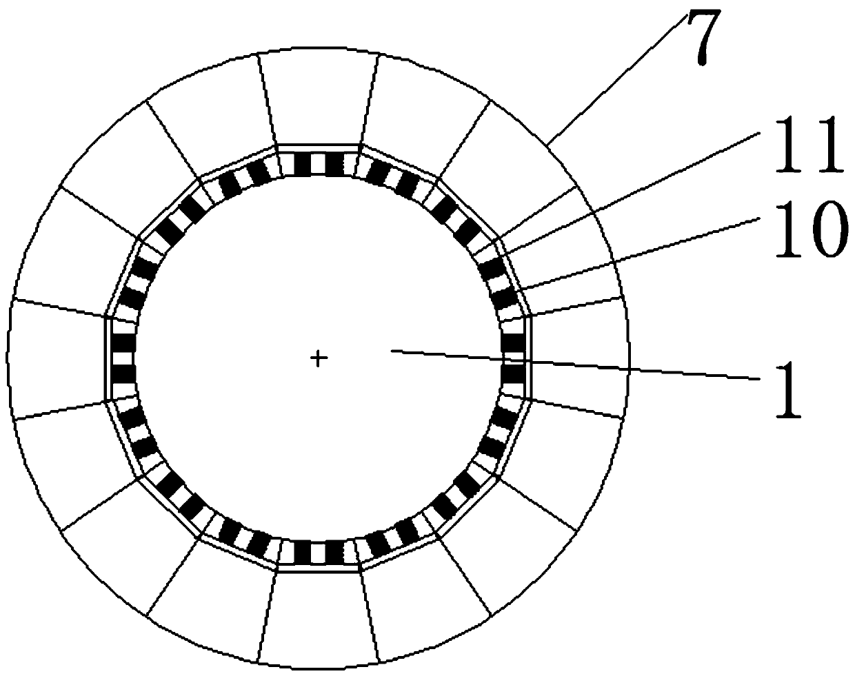
[0056] In combination with Example 1 and figure 2 , image 3 , Figure 4 , The difference from Embodiment 1 is that in this embodiment, the installation and layout of the hydraulic grinding wheel and the main shaft 1 are different. In this embodiment, the hydraulic grinding wheels are evenly distributed around the main shaft 1, and the spherical crown grinding wheels 7 of multiple hydraulic grinding wheels form an annular abrasive belt. At the same time, the spherical crown grinding wheel 7 of the hydraulic grinding wheel is in the shape of a fan-shaped plate, and a plurality of spherical crown grinding wheels 7 in the shape of a fan-shaped plate form an annular grinding wheel.
Embodiment 3
[0058] In combination with Example 1 and figure 2 , image 3 , Figure 4 , Figure 5 , the difference with embodiment 2 is that, in addition to forming the annular grinding wheel, the hydraulic grinding wheel in the annular grinding wheel can rotate, and the present embodiment also includes the following parts;
[0059] The rotating motor 12 is fixedly arranged on the main shaft 1 and is used to drive the hydraulic grinding wheel. At this time, the end face of the spherical crown grinding wheel 71 of the hydraulic grinding wheel is an arc surface;
[0060] A planetary gear 13, one end is connected with the drive shaft of the rotating electrical machine 12, and the other end is meshed with the axial internal teeth of the ring gear 14;
[0061] The ring gear 14, its inner ring side wall is provided with the axial inner teeth meshed with the planetary gear 13, its lower end surface (from Figure 5 Seen from the middle direction) is provided with a face gear matching with the...
PUM
 Abstract
Description
Claims
Application Information
 - R&D Engineer
- R&D Manager
- IP Professional
- Industry Leading Data Capabilities
- Powerful AI technology
- Patent DNA Extraction
Browse by: Latest US Patents, China's latest patents, Technical Efficacy Thesaurus, Application Domain, Technology Topic, Popular Technical Reports.
© 2024 PatSnap. All rights reserved.Legal|Privacy policy|Modern Slavery Act Transparency Statement|Sitemap|About US| Contact US: help@patsnap.com