
Laminated-oriented 3D printer nozzle mechanism

A technology of 3D printers and machine heads, applied in 3D object support structures, coating devices, additive manufacturing, etc., can solve the problems of performance index requirements, poor mechanical properties such as strength and stiffness, and cannot be used in engineering fields, and achieve orientation Controllable, improved comprehensive mechanical properties, and high operability

Active Publication Date: 2019-08-02
SHAANXI UNIV OF SCI & TECH
View PDF11 Cites 0 Cited by
  • Summary
  • Abstract
  • Description
  • Claims
  • Application Information

AI Technical Summary

Problems solved by technology

At present, the products of 3D printers have poor mechanical properties such as strength and stiffness, and cannot be used in the engineering field. Reinforced and modified composite materials are required.
However, when using short fiber reinforcement or one-dimensional / two-dimensional inorganic nanoparticle reinforcement such as carbon nanotubes in the plastic matrix, the orientation distribution of these fillers has a large randomness, resulting in defects in their microstructure and resulting in far inferior mechanical properties. To meet the desired performance index requirements, there is an urgent need for a device that can uniformly disperse short fibers or nanofillers in the matrix component and control the orientation

Method used


Image

  • Laminated-oriented 3D printer nozzle mechanism
  • Laminated-oriented 3D printer nozzle mechanism
  • Laminated-oriented 3D printer nozzle mechanism

Examples


Embodiment Construction

[0020] The present invention will be described in detail below in conjunction with the accompanying drawings and specific embodiments.

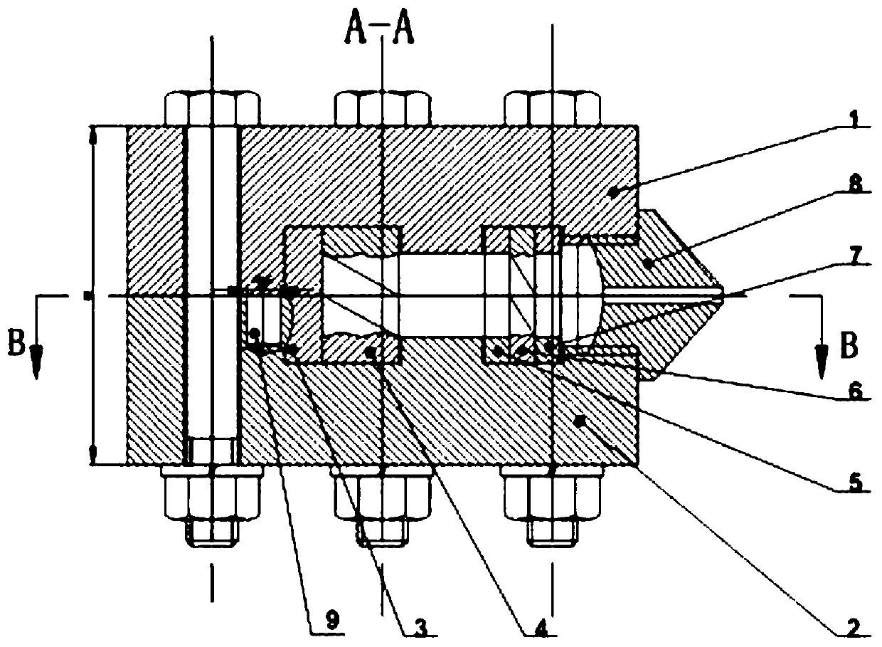
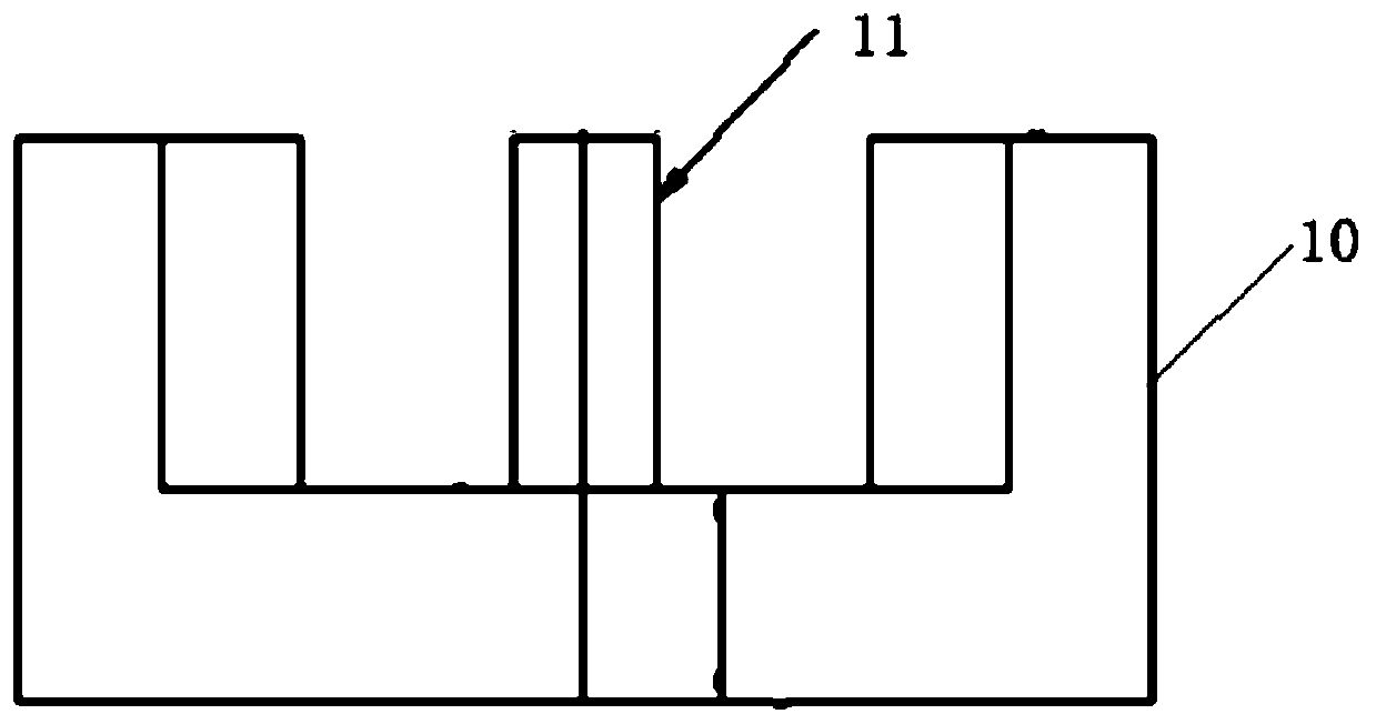
[0021] The present invention is a kind of stack orientation 3D printer spray head mechanism, such as figure 1 As shown, it includes an upper machine head 1 and a lower machine head 2, two positioning bosses 9 are arranged on the inner surface of the upper machine head 1, two positioning grooves are arranged on the inner surface of the lower machine head 2, and the positioning grooves and the positioning The bosses 9 cooperate, the upper machine head 1 and the lower machine head 2 are positioned through the positioning bosses 9, and connected by a plurality of evenly distributed bolts;

[0022] The inside of the upper machine head 1 and the lower machine head 2 are provided with a first internal thread segment, a groove and a second internal thread segment sequentially along the radial direction, and both ends of the groove are connected to th...


PUM

PropertyMeasurementUnit
angleaaaaaaaaaa

Abstract

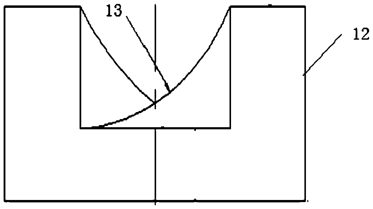
The invention discloses a laminated-oriented 3D printer nozzle mechanism. The mechanism involves an upper machine head and a lower machine head, wherein the upper machine head and the lower machine head are positioned through positioning bosses, a first inner thread section, grooves and a second inner thread section are sequentially arranged in the upper machine head and the lower machine head along the radial direction, the second inner thread section located at the ends of the upper machine head and the end of the lower machine head is connected with an outer thread of a nozzle, a first layering section, a first torsion section, a second layering section, a second torsion section and a confluence section are sequentially arranged in a cavity formed by connecting the grooves of the uppermachine head and the lower machine head in the radial direction. The fused printing wire material flows into a laminated-oriented 3D printer nozzle, then is subjected to the process of layering, twisting, re-layering, re-twisting and confluence, so that the melt can be continuously subjected to strong shearing action, the material can be more uniformly mixed; and meanwhile, the orientation state of the high polymer is more obvious, so that the mechanical property of the material is improved.

Description

technical field [0001] The invention belongs to the technical field of 3D printing equipment, and in particular relates to a nozzle mechanism of a stacked orientation 3D printer. Background technique [0002] 3D printing is to form the required parts by layer-by-layer accumulation of materials. Based on the digital three-dimensional CAD model file, specific materials such as filaments and sheets are stacked layer by layer. This molding method has low manufacturing cost, Short production cycle and other advantages. At present, the products of 3D printers have poor mechanical properties such as strength and stiffness, and cannot be used in the engineering field very well. Reinforced and modified composite materials need to be used. However, when using short fiber reinforcement or one-dimensional / two-dimensional inorganic nanoparticle reinforcement such as carbon nanotubes in the plastic matrix, the orientation distribution of these fillers has a large randomness, resulting in...

Claims


Application Information

Patent Timeline
Patent Type & Authority Applications(China)
IPC IPC(8): B29C64/118B29C64/209B33Y30/00
CPCB33Y30/00B29C64/118B29C64/209
Inventor 于旻葛正浩孙立新衡冲
Owner SHAANXI UNIV OF SCI & TECH
Learn More