Rotary spiral gas anchor

A spiral and gas anchor technology, which is applied in the direction of production fluid, wellbore/well components, earthwork drilling and production, etc., can solve the problems of short validity period of the packer, inability to adapt to high liquid production, low separation efficiency, etc., and achieve frictional resistance Smaller, lower relative speed, better separation efficiency

Pending Publication Date: 2019-08-02
YANGTZE UNIVERSITY
View PDF1 Cites 2 Cited by
  • Summary
  • Abstract
  • Description
  • Claims
  • Application Information

AI Technical Summary

Problems solved by technology

Disadvantages: low separation efficiency, not suitable for production wells with high liquid production and high gas-oil ratio
However, due to the packer, the construction is inconvenient and the packer has a short validity period, which affects production. In addition, sand production wells cannot be used

Method used


Image

  • Rotary spiral gas anchor
  • Rotary spiral gas anchor
  • Rotary spiral gas anchor

Examples


Embodiment Construction

[0036] The implementation of the present invention will be described in detail below in conjunction with the examples of implementation, but they do not constitute a limitation of the present invention, and are only examples. At the same time, the advantages of the present invention will become clearer and easier to understand.

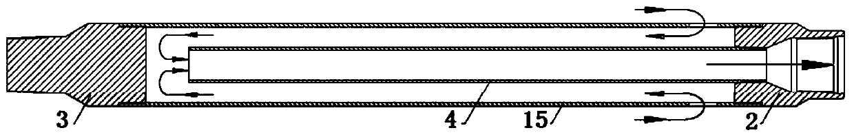
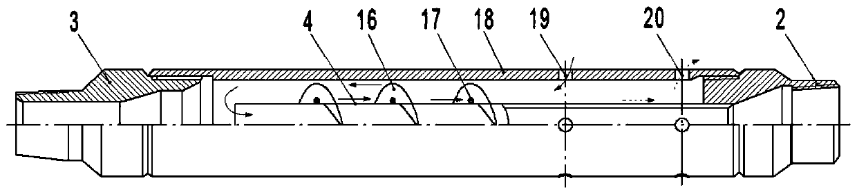
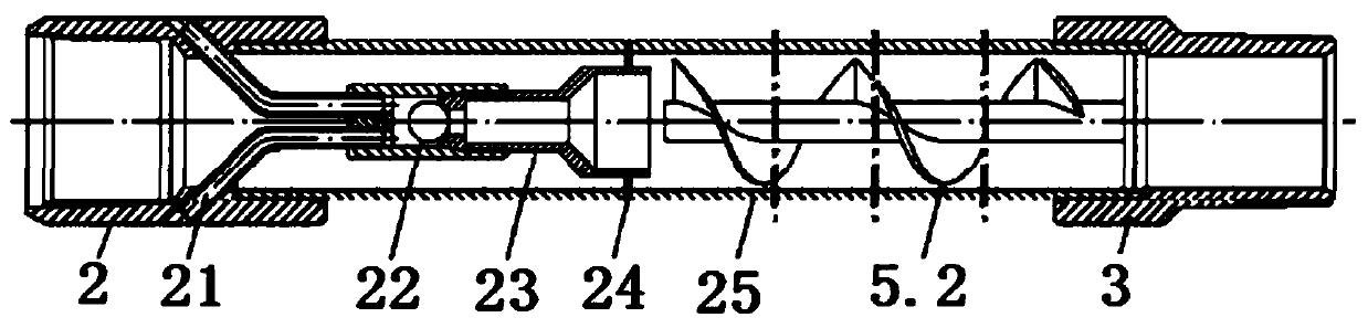
[0037] Such as Figure 6 A rotary screw type air anchor shown includes an anchor housing 1, one end of the anchor housing 1 is provided with an upper joint 2, and the other end is provided with a lower joint 3, and one end of the anchor housing 1 is connected to the upper joint 2 are threaded, and the other end is threaded with the lower joint 3. Internal threads 12 are provided on the inner walls of both ends of the anchor housing 1 , and external threads 13 matching the internal threads 12 are provided on the outer walls of the upper joint 2 and the lower joint 3 . The anchor housing 1 is provided with a central tube 4 extending in the axial direc...


PUM


Abstract

The invention discloses a rotary spiral gas anchor. The gas anchor comprises an anchor shell, an upper connector is arranged at one end of the anchor shell, a lower connector is arranged at the otherend of the anchor shell, a central pipe extending in the axial direction is arranged in the anchor shell, and a spiral body is rotatably arranged in the middle of the central pipe; one end of the spiral body is installed on the central pipe through a first rotating piece, and the other end of the spiral body extends towards the upper connector and is installed on the central pipe through a secondrotating piece; an annular installation step is arranged on the outer ring of the end, close to the lower connector, of the central pipe and abuts against the first rotating piece; and the outer ringof the end, close to the upper connector, of the central pipe is sleeved with a compression spring, one end of the compression spring abuts against the second rotating piece, and the other end of thecompression spring abuts against the upper connector. The rotary spiral gas anchor is impacted by gas and liquid fluid to rotate, and the gas and liquid can be separated more efficiently through the rotating spiral body.

Description

technical field [0001] The invention relates to the technical field of petroleum exploration and production, in particular to a rotary spiral gas anchor. Background technique [0002] In the field of oil exploration and production, because the fluid in the block with high gas-liquid ratio contains a large amount of free gas, the gas seriously affects the pump efficiency when the oil pump is used to recover the oil, so it is necessary to use a gas anchor to separate the gas in the gas-liquid mixed fluid , to reduce the impact of gas on pump efficiency. The main types of existing air anchors are gravity difference separated air anchors, spiral air anchors and combined air anchors, as follows: [0003] 1. Gravity difference separated air anchor, also known as gravity air anchor, such as figure 1 , mainly consists of upper joint 2, anchor outer body 15, central tube 4, lower joint 3 and so on. The principle is to separate the gas phase by using the slippage effect produced by...

Claims


Application Information

Patent Timeline
Patent Type & Authority Applications(China)
IPC IPC(8): E21B43/38
CPCE21B43/38
Inventor 廖锐全张慢来张昭刘自龙
Owner YANGTZE UNIVERSITY
Why Eureka
Try Eureka