Cam shaft of engine and air valve driving device

A driving device and engine technology, applied in the direction of engine components, engine control, machine/engine, etc., can solve the problems of high cost, complex structure, poor reliability, etc., to achieve simple structure, ensure reliability, and avoid impact damage to the valve system. Effect

Active Publication Date: 2019-08-02
苏州三林万腾汽车科技有限公司
View PDF7 Cites 19 Cited by
  • Summary
  • Abstract
  • Description
  • Claims
  • Application Information

AI Technical Summary

Problems solved by technology

[0004] In order to solve the problems of complex structure, high cost and poor reliability in the prior art, the present invention provides a camshaft of an engine and a valve driving device equipped with such a camshaft. Valve, the present invention has a special design for the camshaft structure and valve driving device, which can ensure that the roller can reliably realize switching contact with different cams, and the design structure of the present invention is simple, low in cost and easy to apply

Method used


Image

  • Cam shaft of engine and air valve driving device
  • Cam shaft of engine and air valve driving device
  • Cam shaft of engine and air valve driving device

Examples


Embodiment Construction

[0030] The specific technical solutions adopted in the embodiments of the present invention will be described in detail and completely below in conjunction with the accompanying drawings of the present invention. In the description of the present invention, unless otherwise specified, the meaning of "multiple" refers to two or two The orientations or positional relationships indicated by the terms "upper", "lower", "left", "right", "inner" and "outer" used above are only for the convenience of describing and explaining the present invention based on the appended drawings of the present invention. The orientation or positional relationship shown in the figure should not be interpreted as a specific orientation or positional relationship that the referred devices or elements must have, and therefore does not constitute a limitation to the present invention.

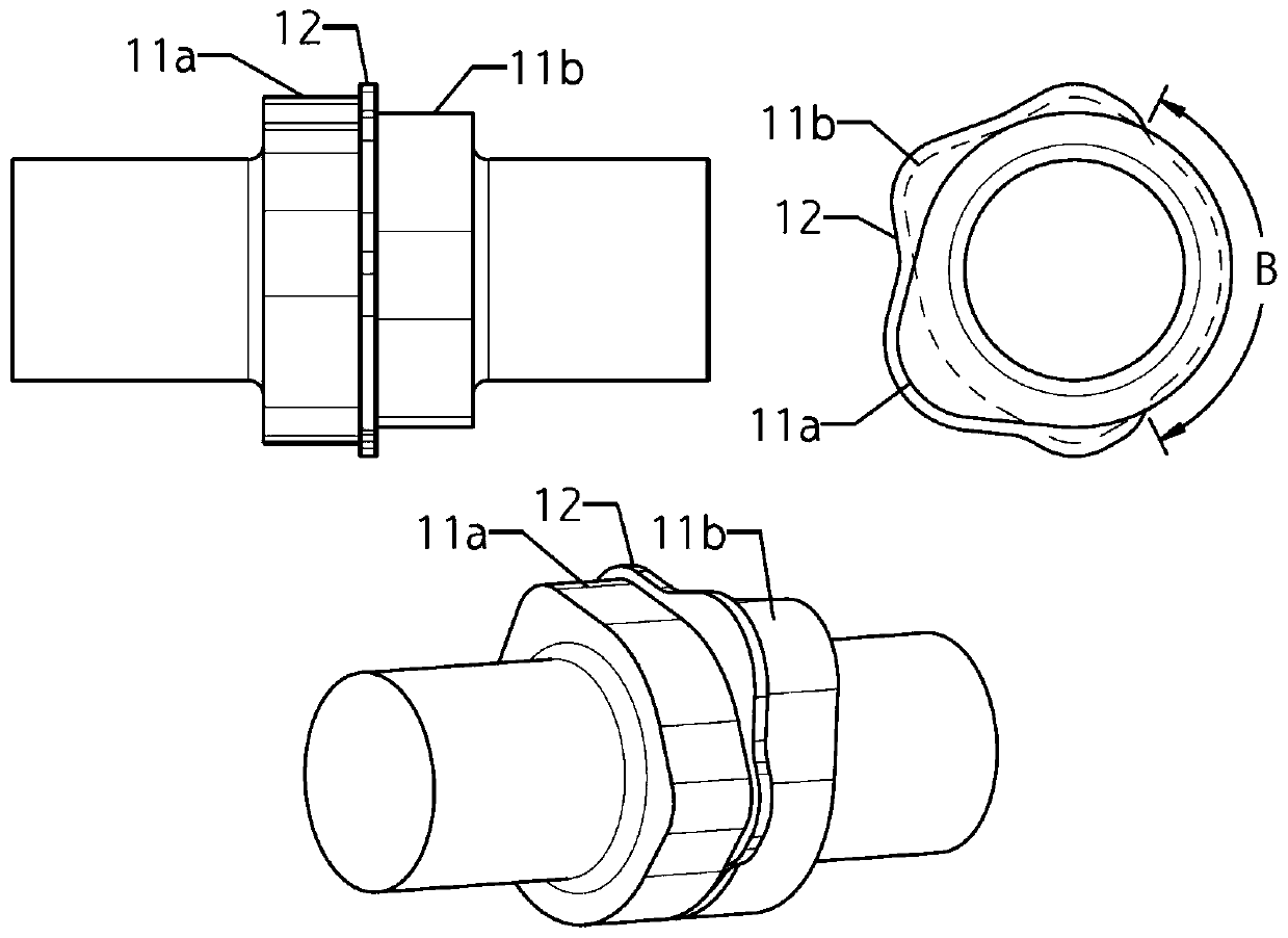
[0031] As a first aspect of the present invention, a camshaft of an engine is provided, figure 1A first embodiment of the...


PUM


Abstract

The invention relates to a cam shaft of an engine and an air valve driving device. The cam shaft is structured such that an air inlet or exhaust rocker arm is provided with first cam and second cam adjacent to each other. A flange is arranged between the two cams. A lift part is arranged on each of the two cams. The flange is not arranged in parts, as base circles, of the two cams. A rocker arm roller can be driven by an actuator driven by compressed air to slide on a roller shaft to switch contact between the two cams. An ECU determines an electrifying moment of an electromagnetic valve according to a signal of cam shaft position sensor to control on-off of a compressed air pipeline connected to the actuator. When the rocker arm roller is switched to the other cam, as a result of blockageby the flange, only when the cam shaft rotates to the part, as the basic circle, of the two cams, the cams can be switched, so that the reliability is ensured. A plurality of actuators can be controlled by one electromagnetic valve. The cam shaft is low in cost. The two cams can be used for achieving functions needed by the engine, for example, variable air valve or engine brake.

Description

technical field [0001] The invention relates to the technical field of engines, in particular to a camshaft and a valve driving device of an engine. Background technique [0002] There are many kinds of engine variable valve technologies known at present. Various variable valve technologies realize variable valve lift or valve timing through different structural designs and control methods, so that the engine can obtain better performance or realize A special feature, of which a known class of variable valve technology is achieved by providing two cams with different profiles on the camshaft of the engine, and having the valve drive mechanism switch between the two different cams as required The engine gets two different valve lifts to improve engine performance or to achieve a special function such as engine braking. [0003] For this type of variable valve mechanism with switchable cams, a currently disclosed design is for a rocker arm mechanism with a roller follower, so...

Claims


Application Information

Patent Timeline
Patent Type & Authority Applications(China)
IPC IPC(8): F01L1/047F01L1/18F01L13/00F01L9/02F02D13/02F01L9/10F01L9/14F01L9/16
CPCF01L1/047F01L1/18F01L13/0036F02D13/0207F02D2013/0296F01L9/16F01L9/10F02D41/009F01L1/181
Inventor 姬腾飞
Owner 苏州三林万腾汽车科技有限公司
Why Eureka
Try Eureka