Electronic water pump
A technology of electronic water pump and pump casing, applied in the direction of pump, pump control, pump device, etc., can solve problems such as poor heat dissipation effect, achieve the effect of improving life and reliability, preventing rotor from being stuck, and improving motor efficiency
- Summary
- Abstract
- Description
- Claims
- Application Information
AI Technical Summary
Problems solved by technology
Method used
Image

Examples
Embodiment 1
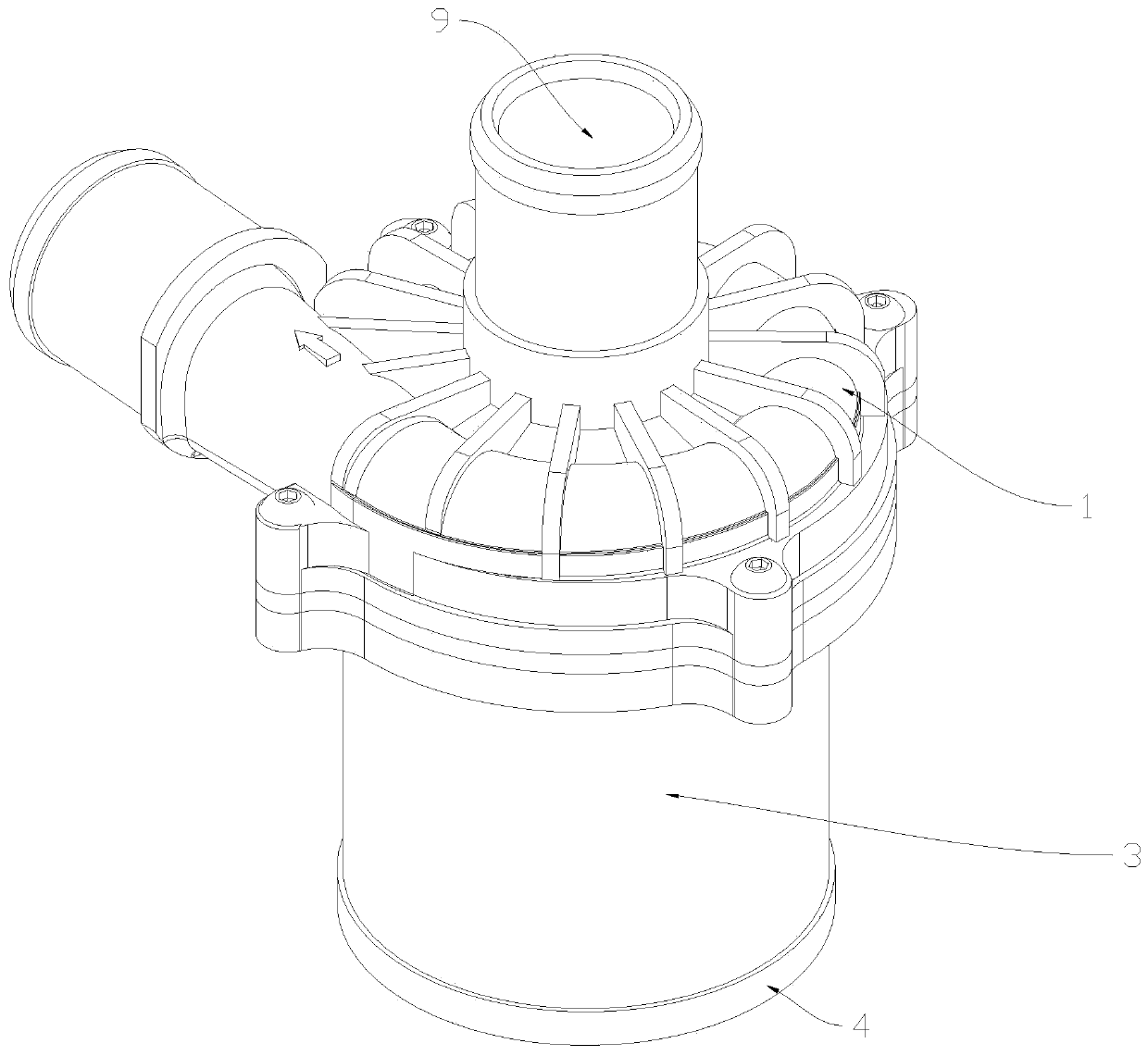
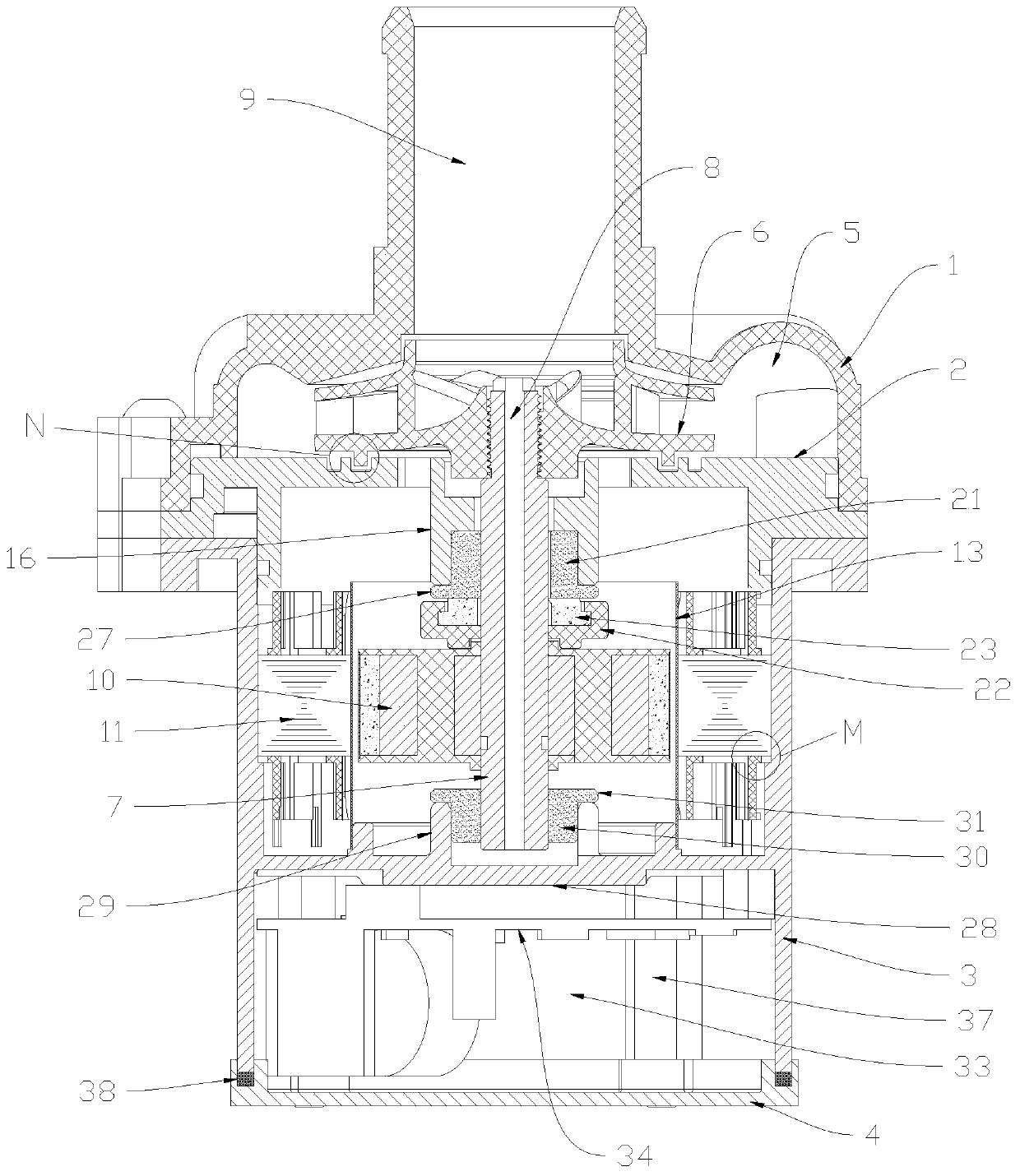
[0033] An electronic water pump such as Figure 1 to Figure 13 As shown, it includes a pump cover 1, a front cover 2, a pump casing 3, and a bottom cover 4 connected sequentially from top to bottom. A working chamber 5 is formed between the pump cover 1 and the front cover 2, and an impeller 6 is arranged in the working chamber 5. The pump casing 3 is provided with a pump shaft 7 located at the center of the pump casing 3. The upper end of the pump shaft 7 is connected to the impeller 6 and drives the impeller 6 to rotate synchronously. The upper end communicates with the working chamber 5, the lower end of the central through hole 8 communicates with the inside of the pump casing 3, and the pump cover 1 is provided with a water inlet 9 integrated with the pump cover 1, and the water inlet 9 communicates with the working chamber 5. The upper end of the pump shaft 7 is provided with an external thread, and the pump shaft 7 and the impeller 6 are threaded to facilitate disassemb...
Embodiment 2
[0039] An electronic water pump such as Figure 1 to Figure 13 As shown, on the basis of Embodiment 1, a sealing groove 14 is provided on the upper end surface of the front cover 2, and a sealing ring 15 matching the sealing groove 14 is arranged in the sealing groove 14, and the sealing ring 15 is arranged under the impeller 6, Below the middle part of the front cover 2, there is an installation section 16 with an integrated structure with the front cover 2. The installation section 16 extends from top to bottom, and the pump shaft 7 runs through the installation section 16. The installation section 16 is provided with impellers in sequence from top to bottom. The installation groove 17, the pump shaft through hole 18, the bearing installation groove 19, the lower end of the impeller 6 is fitted in the impeller installation groove 17, the bearing installation groove 19 is provided with the front bearing 20 adapted to the bearing installation groove 19, and there are 20 sets of...
Embodiment 3
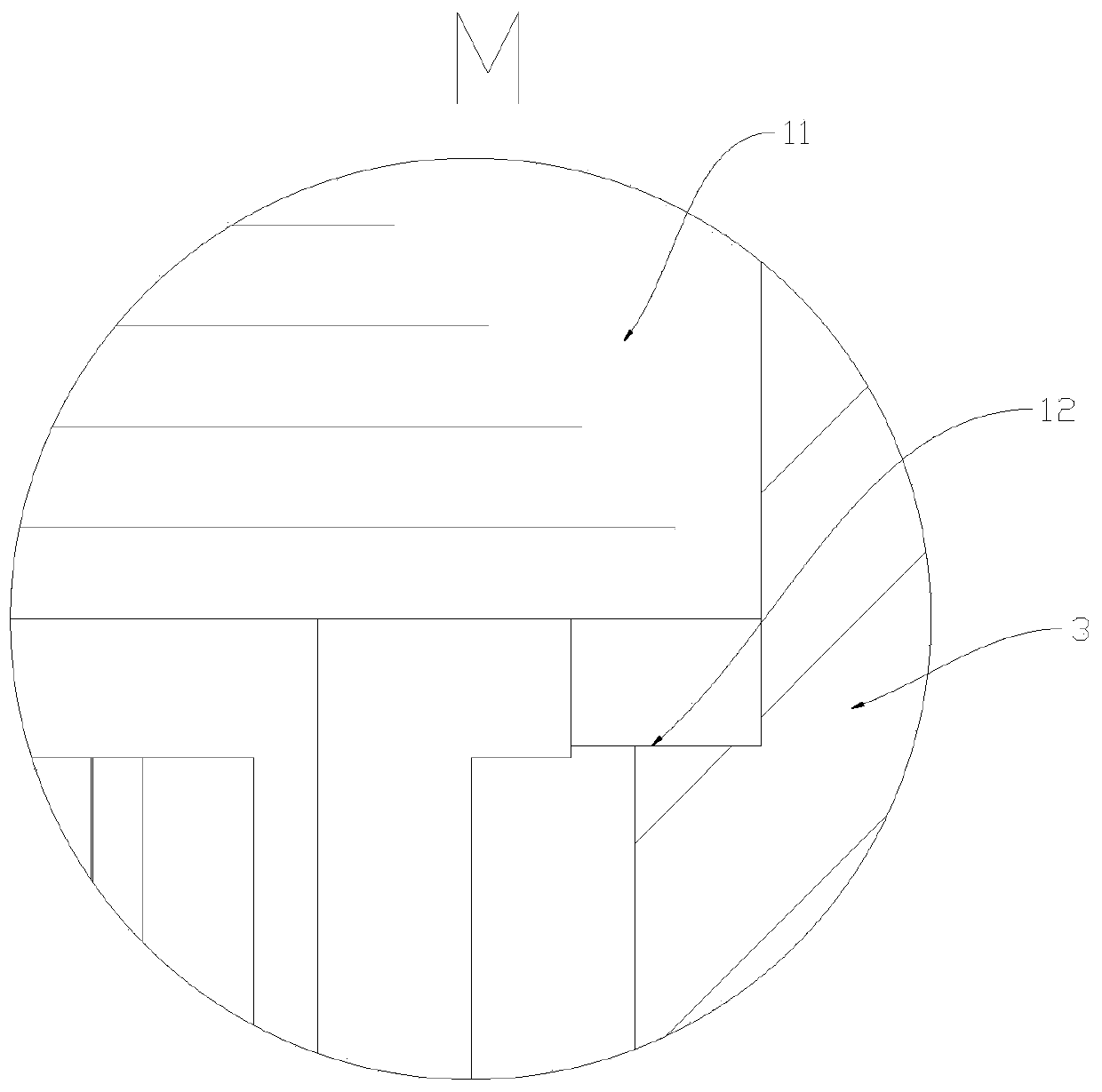
[0043] An electronic water pump such as Figure 1 to Figure 13 As shown, on the basis of Embodiment 2, a bottom plate 28 is provided in the middle of the pump casing 3, a rear bearing seat 29 is provided on the bottom plate 28, and a rear bearing 30 adapted to the rear bearing seat 29 is provided in the rear bearing seat 29. , the rear bearing 30 is sleeved on the lower end of the pump shaft 7, the upper end of the rear bearing 30 is provided with an annular positioning ring 31, the annular positioning ring 31 is offset against the upper end of the rear bearing seat 29, and the side wall of the rear bearing seat 29 is provided with an annular spacer The opening groove 32 that cloth is arranged, the opening groove 32 is vertically arranged on the rear bearing seat 29. The rear bearing 30 is positioned inside the upper end of the rear bearing seat 29 through the annular positioning ring 31, so that after the working medium enters the inside of the pump casing 3, the working medi...
PUM
 Abstract
Description
Claims
Application Information
 - R&D
- Intellectual Property
- Life Sciences
- Materials
- Tech Scout
- Unparalleled Data Quality
- Higher Quality Content
- 60% Fewer Hallucinations
Browse by: Latest US Patents, China's latest patents, Technical Efficacy Thesaurus, Application Domain, Technology Topic, Popular Technical Reports.
© 2025 PatSnap. All rights reserved.Legal|Privacy policy|Modern Slavery Act Transparency Statement|Sitemap|About US| Contact US: help@patsnap.com