Wire placing brick and low-heat-waste and high-heat-efficiency electric heating structure

A high thermal efficiency technology for wire bricks, applied in the fields of wire bricks, high thermal efficiency electric heating structures, wire bricks and low heat loss, can solve the problems of large heat loss of heating devices, large heat storage of furnace walls, and short service life. Achieve the effects of high thermal efficiency, small heat storage in the furnace wall and long service life

Pending Publication Date: 2019-08-02
GUANGDONG STRONG METAL TECH
View PDF0 Cites 0 Cited by
  • Summary
  • Abstract
  • Description
  • Claims
  • Application Information

AI Technical Summary

Problems solved by technology

[0004] One of the purposes of the present invention is to provide a wire brick structure in order to solve the problems of large furnace wall heat storage, large heat loss of heating devices, low thermal efficiency and short service life in the prior art wire brick structure.

Method used


Image

  • Wire placing brick and low-heat-waste and high-heat-efficiency electric heating structure
  • Wire placing brick and low-heat-waste and high-heat-efficiency electric heating structure
  • Wire placing brick and low-heat-waste and high-heat-efficiency electric heating structure

Examples


specific Embodiment 1

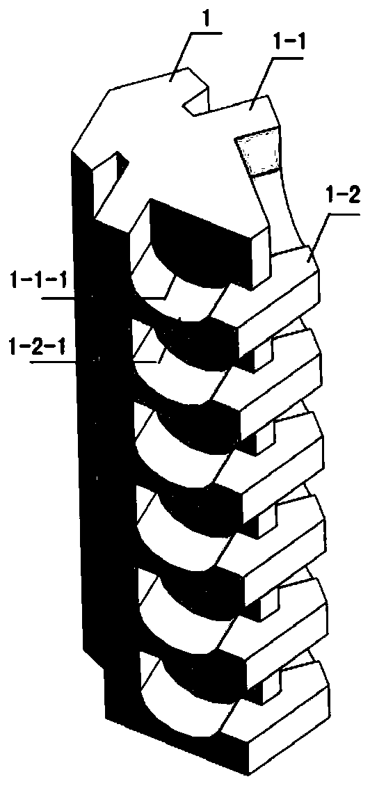
[0027] refer to figure 1 , the threaded brick involved in this embodiment 1 includes a brick body 1, the upper part 1-1 of the brick body 1 has an approximate "T" shape structure, the bottom is a platform structure 1-2, and the platform structure 1-2 An upward arc-shaped groove 1-2-1 is provided on both sides, and a downward arc-shaped groove 1-1-1 is respectively provided on both sides of the bottom surface of the upper part 1-1 of the brick body 1, forming a space for installing electric heating devices from both sides. Structure; the projected area of ​​the upper part 1-1 of the brick body 1 is relatively small, forming an easy-to-embed and take-out structure of the electric heating device. A three-dimensional wire brick structure can be formed by stacking several wire bricks.

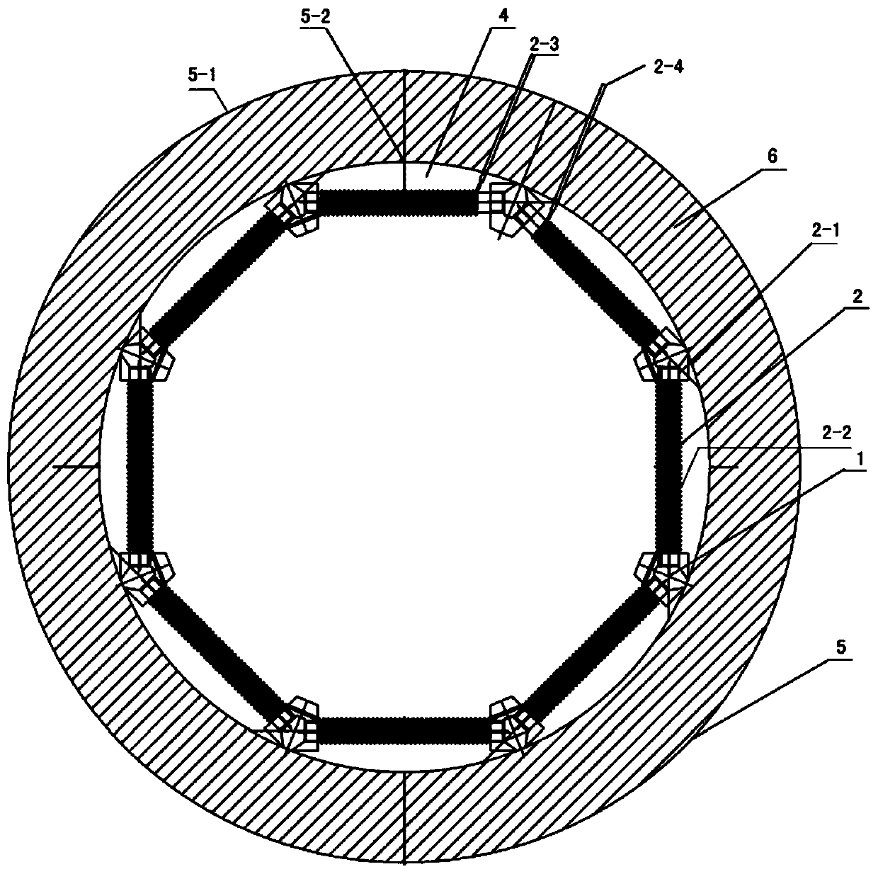
[0028] refer to figure 2 The electric heating structure with low heat loss and high thermal efficiency involved in this embodiment 1 includes several wire bricks, the upper part 1-1 of the brick ...

specific Embodiment 2

[0038] The feature of this specific embodiment 2 is: in the polygonal structure connected by the electric heating device 2, it includes a triangular structure, a quadrilateral structure, a pentagonal structure, a hexagonal structure, a decagonal structure or more than twelve according to the size of the inner wall. polygonal structure. All the other are with specific embodiment 1.


PUM


Abstract

The invention relates to a wire placing brick and a low-heat-waste and high-heat-efficiency electric heating structure. The structure comprises a plurality of brick bodies, the brick bodies are characterized in that the upper portion of each brick body is provided with a structure similar to a T shape, the bottom is of a platform structure, an upward arc-shaped groove is formed in each of the twosides of the platform structure, and a downward arc-shaped groove is formed in each of the two sides of the bottom face of the upper portion of the brick body so as to install the structures of electric heating members from the two sides; the upper portion of the brick body is provided with a structure which is easily embedded and taken out of the electric heating member; the formed low-heat-wasteand high-heat-efficiency electric heating structure comprises a plurality of wire placing bricks, the wire placing bricks are distributed at polygonal connecting points and are connected as a polygonal structure through the electric heating members, the wire placing bricks are fixedly connected to form a stable polygon through fixing members, and the electric heating members are connected end toend to form a polygonal electric heating structure; the electric heating members are not in contact with an inner cavity of a furnace body to form a low-heat-waste and high-radiation thermal-efficiency electric heating structure. The structure has the advantages that the furnace wall heat storage capacity is low, the heat loss of the heating members is low, the thermal efficiency is high, and theservice life is long.

Description

technical field [0001] The invention relates to a wire shelf brick, in particular to a wire shelf brick and an electric heating structure with low heat loss and high thermal efficiency. It belongs to the technical field of metal heat treatment equipment. Background technique [0002] At present, industrial furnaces are widely used in industries such as metallurgy, casting, heat treatment and forging, and according to statistics, their energy consumption accounts for more than 80% of the professional thermal processing factories. Therefore, improving the thermal efficiency of industrial furnaces, reducing energy loss, and prolonging the life of the furnace and its electrothermal structure are one of the key points in the research of industrial furnaces. The industrial furnace structure includes furnace lining, furnace frame, heating device, furnace machinery and control system. The furnace lining is composed of refractory materials, heat insulation materials and building ma...

Claims


Application Information

Patent Timeline
IPC IPC(8): F27D1/04F27D11/02
CPCF27D1/04F27D11/02
Inventor 王桂茂
Owner GUANGDONG STRONG METAL TECH
Why Eureka
Try Eureka