Split-Hopkinson tension bar test piece fixture and mounting method

A separate, test piece technology, applied in the direction of measuring devices, analyzing materials, and using stable tension/pressure to test the strength of materials, etc., can solve the problems of high test accuracy and unlimited test piece materials, and achieve a wide range of applications , high test data accuracy and precision, and easy installation

Inactive Publication Date: 2019-08-02
MAANSHAN IRON & STEEL CO LTD
View PDF8 Cites 2 Cited by
  • Summary
  • Abstract
  • Description
  • Claims
  • Application Information

AI Technical Summary

Problems solved by technology

[0007] The purpose of the present invention is to overcome the shortcomings of the existing separated Hopkinson tie rods that the connection between the test piece and the tie rod is difficult to meet the shortcomings of convenient installation, high test accuracy and unlimited material of the test piece, and provides a separate Hopkinson tie rod. Jinsen pull rod test piece fixture and clamping method

Method used


Image

  • Split-Hopkinson tension bar test piece fixture and mounting method
  • Split-Hopkinson tension bar test piece fixture and mounting method
  • Split-Hopkinson tension bar test piece fixture and mounting method

Examples


Embodiment 1

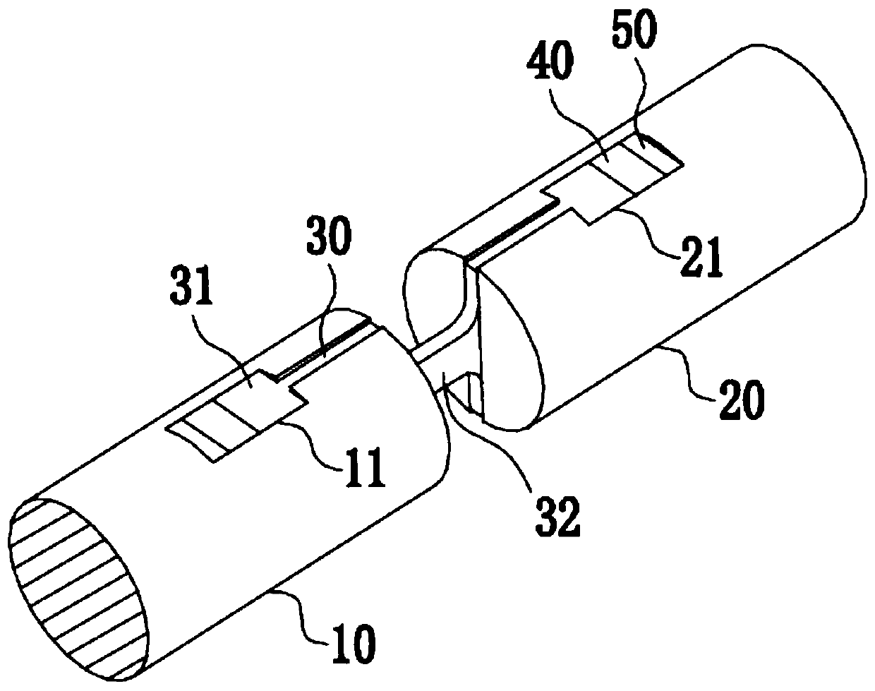
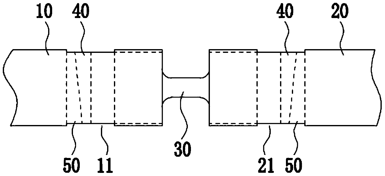
[0050] A separate Hopkinson tie rod specimen fixture, such as figure 1 , 2 As shown, it includes: an incident rod 10, one end of which is provided with a slot I11 for clamping a test piece 30; and a transmission rod 20, one end of which is provided with a slot II21 for clamping a test piece 30; Block B50, which cooperates with each other to fill in the gap between the two ends of the test piece 30 and the slot I11 and slot II21. The purpose of reserving the gap between the slot I11 and the bottom surface of the slot II21 is to facilitate the clamping of the test piece 30 .

[0051] When loading the test piece 30, firstly snap the two ends of the test piece 30 into the slots I11 and II21 respectively, and then insert the wedge block A40 and the wedge-shaped Block B50, when clamping wedge-shaped block A40 and wedge-shaped block B50, insert wedge-shaped block A40 and wedge-shaped block B50 from the notches on both sides of the card slot I11 and card slot II21 respectively, and ...

Embodiment 2

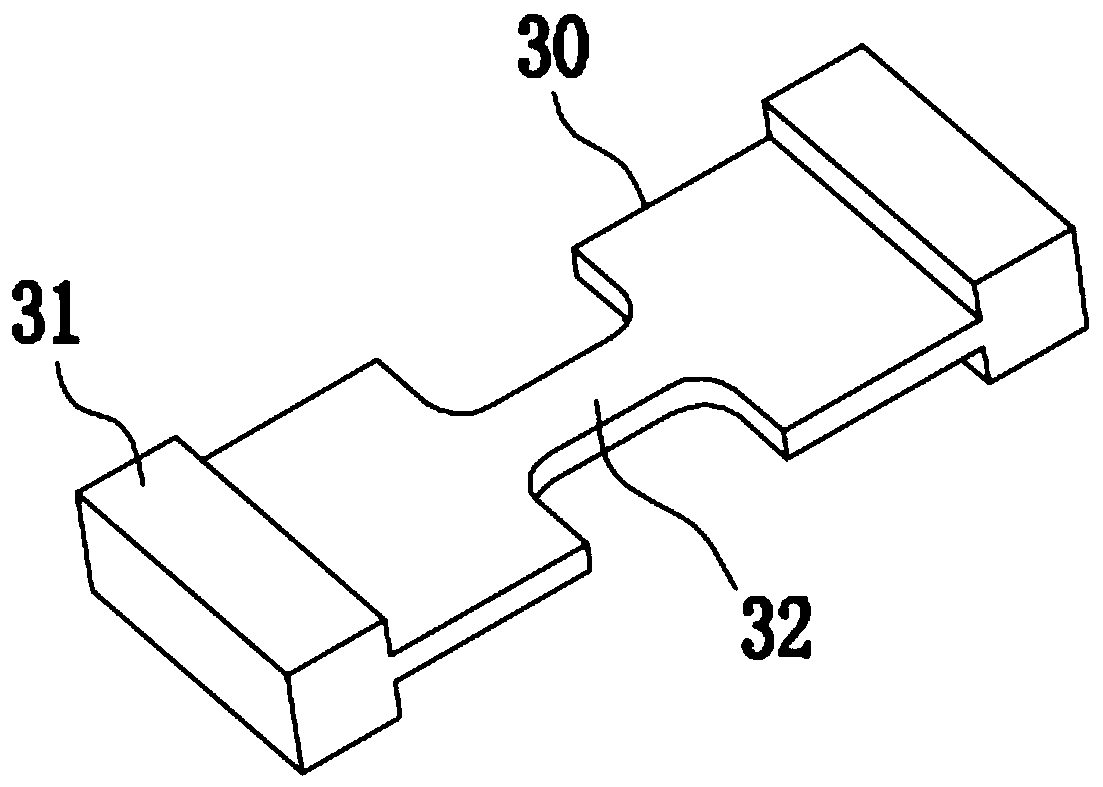
[0055] A kind of split-type Hopkinson rod test piece fixture of the present embodiment, the basic structure is the same as that of embodiment 1, the differences and improvements are as follows: figure 1 As shown, the said slot I11 and slot II21 are both "T" shaped through slots arranged radially along the rod. During the test, as image 3 As shown, the two ends of the test material are processed into a test piece 30 with a "T"-shaped connection end matched with the through groove. Since this structure is relatively simple, it is very easy to process.

Embodiment 3

[0057] A kind of split-type Hopkinson rod test piece fixture of the present embodiment, the basic structure is the same as that of embodiment 1 or 2, the differences and improvements are as follows: figure 1 As shown, the incident rod 10 and the transmission rod 20 are arranged coaxially, so that during the test, the tensile force of the incident rod 10 and the transmission rod 20 on the test piece 30 is collinear and opposite, preventing the test piece 30 from being biased due to force. Torque is generated to ensure the accuracy and precision of the test.


PUM


Abstract

The invention discloses a split-Hopkinson tension bar test piece fixture and mounting method, and belongs to the technical field of material dynamic mechanical tests. The fixture comprises an incidentbar, one end of which being provided with a neck I for mounting a test piece; a transmission bar, one end of which being provided with a neck II for mounting the test piece; and wedge blocks A and wedge blocks B, which are fitted to each other and are filled in neck gaps between the two ends of the test piece and the neck I and the neck II; the neck I and the neck II are both "T" shaped through grooves disposed along the radial direction of the bar; the incident bar and the transmission bar are the coaxially disposed; two wedge blocks A and two wedge blocks B are provided; and the wedge blocks A and the wedge blocks B are combined to form a rectangle. When the test piece is mounted, the both ends of the test piece are respectively clamped in the neck I and the neck II at first, and then the wedge blocks A and the wedge blocks B are mounted, so that the test piece is in no clearance fit with the neck I and the neck II. By adopting the split-Hopkinson tension bar test piece fixture disclosed by the invention, fast mounting of the test piece can be achieved, so that the test efficiency is greatly improved, and the test data accuracy is high; and the test piece is easy to process, andthe material is not limited.

Description

technical field [0001] The invention relates to the technical field of material dynamic mechanics testing, in particular to a separate Hopkinson rod test piece fixture and a clamping method. Background technique [0002] Studying the dynamic mechanical behavior of materials at high strain rates plays an important role in the research and design of crash safety of automobiles. The strain rates in dynamic shock events cover a wide range from quasi-static to 5000s-1. Accurately obtaining the mechanical response of materials in the entire strain rate range, especially the mechanical response of materials under dynamic high strain rates is the key to material characterization. [0003] At present, the experimental equipment applied to the dynamic mechanical properties of materials mainly includes high-speed tensile testing machines and separate Hopkinson tie rods. The electro-hydraulic servo high-speed testing machine has good test results in the range of medium and low strain ...

Claims


Application Information

Patent Timeline
Patent Type & Authority Applications(China)
IPC IPC(8): G01N3/04G01N3/08
CPCG01N3/04G01N3/08G01N2203/04
Inventor 张军吴海龙田志俊何浪赖兴华
Owner MAANSHAN IRON & STEEL CO LTD
Why Eureka
Try Eureka