Boring tool used for machining small-hole-diameter step type round hole inner cavity and provided with replaceable tool head

A technology of small aperture and cutter head, which is applied in the direction of tools, manufacturing tools, metal processing equipment, etc. for lathes, can solve the problems of low processing efficiency, easy deviation of processing concentricity, etc., so as to improve processing efficiency and processing quality. Effect

Pending Publication Date: 2019-08-06
SHANXI FENXI HEAVY IND
0 Cites 0 Cited by

AI-Extracted Technical Summary

Problems solved by technology

[0003] The invention provides a boring tool for machining the inner cavity of a circular hole with a small diameter and a step, which solves the problem that the processing...

Method used

A kind of boring tool that is used to process the replaceable cutter head of the circular hole inner cavity of small aperture band, comprises cutter bar (1) and cutter head seat (2), is provided with barrel on cutter bar (1) shaped cavity (3), the cavity mouth (4) of the barrel-shaped cavity (3) is connected with a cutter head seat (2), and the cutter head seat (2) is respectively provided with connecting threads for the cutter head and the cutter bar (6) and the annular positioning step (9), the cutter head seat (2) is screwed in the cavity mouth (4) through the connecting thread (6) of the cutter head and the cutter rod, and the central axis of the annular positioning ...

Abstract

The invention discloses a boring tool used for machining a small-hole-diameter step type round hole inner cavity and provided with a replaceable tool head. The technical problems that when an inner hole inner cavity provided with a step is subjected to high-speed boring machining, the machining concentricity is prone to deviating, and the machining efficiency is low are solved. A tool rod (1) is provided with a barrel-shaped cavity (3), and a cavity opening (4) of the barrel-shaped cavity (3) is connected with a tool head seat (2). The boring tool is characterized in that the tool head seat (2) is provided with a tool head and tool rod connection thread (6) and an annular positioning step (9), and the tool head seat (2) and the tool head and tool rod connection thread (6) are connected into the cavity opening (4); the axis (10) of the annular positioning step (9) coincides with the axis (11) of the tool rod (1); and a tool blade (7) is fixed to the tool head seat (2) through a jackscrew (8). The machining efficiency and the machining quality are greatly improved.

Application Domain

Boring barsTurning tools

Technology Topic

Image

  • Boring tool used for machining small-hole-diameter step type round hole inner cavity and provided with replaceable tool head
  • Boring tool used for machining small-hole-diameter step type round hole inner cavity and provided with replaceable tool head
  • Boring tool used for machining small-hole-diameter step type round hole inner cavity and provided with replaceable tool head

Examples

  • Experimental program(1)

Example Embodiment

[0014] The present invention will be described in detail below in conjunction with the drawings:
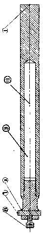
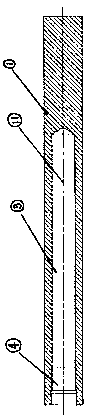
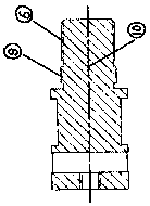
[0015] A boring tool with a replaceable cutter head used for processing the inner cavity of a small-diameter round hole with a stepped hole. The boring tool includes a cutter bar (1) and a cutter head holder (2). A barrel-shaped cavity is provided on the cutter bar (1) (3) A cutter head holder (2) is connected to the cavity port (4) of the barrel-shaped cavity (3), and the cutter head and cutter rod connecting threads (6) are respectively provided on the cutter head holder (2) And the annular positioning step (9), the cutter head seat (2) is screwed into the cavity port (4) through the connecting thread (6) of the cutter head and the cutter rod, and the central axis (10) of the annular positioning step (9) It is coincident with the center axis (11) of the tool bar (1), and the blade (7) is fixed on the cutter head seat (2) through the top wire (8); when machining the hole-shaped cavity, it encounters For stepped holes, only need to unscrew the tool head holder (2) and replace with another tool head holder of the size corresponding to the stepped hole to continue processing. There is no need to replace the tool holder, which avoids re-clamping and centering of the tool Positioning improves the machining accuracy and efficiency; the tool holder and tool head adopt high-precision positioning step surfaces to ensure the perfect combination of tool holder and tool head.
[0016] The barrel-shaped cavity (3) is filled with lead or copper eccentric spherical particles (5), the diameter of the eccentric spherical particles (5) is 3.5 mm, and the total volume of the filled eccentric spherical particles (5) The ratio of the volume to the barrel-shaped cavity (3) is 70:100.
[0017] The barrel-shaped cavity (3) is filled with copper powder, and the ratio of the volume of the filled copper powder and the eccentric spherical particles (5) to the volume of the barrel-shaped cavity (3) is 70:100, so The ratio of the volume of the canned copper powder to the volume of the filled eccentric spherical particles (5) is 1:5.
[0018] When the exciting force is small or instantaneously excited, the relative motion speed between the eccentric spherical particles (5) will be very small, and the eccentric spherical particles (5) and its copper powder in the cavity will mainly slide relatively In this state, the eccentric sphere particles (5) are mainly frictional energy dissipation; when the excitation force increases or continuous excitation force is applied, the eccentric sphere particles (5) will accelerate and rotate at high speed due to the eccentricity. For movement, the tool holder mainly relies on the plastic deformation of the eccentric spherical particles (5) colliding with the inner wall of the tool holder to absorb energy, that is, the so-called changing the dynamic stiffness of the tool to avoid resonance.
[0019] The material of the tool shank and the tool head of the present invention is selected (W6 high-speed steel) and quenched to a hardness of 63-66 HRC to increase the hardness. In the present invention, a lead ball or a copper ball is selected as the damping particles. The specific parameters are as follows:
[0020] Damping material name density Elastic Modulus Shear modulus Features copper 8.9 108 39 Good plasticity lead 11.34 17 7 Good plasticity
[0021];
[0022] When the speed of the vibration reduction tool is not high, the vibration reduction effect is mainly achieved by the strength of the material of the tool holder. At this time, the movement of the damping particles and the inner cavity wall is mainly sliding friction to absorb energy. When the speed continues to increase That is, when resonance is reached, the damping particles in the inner cavity mainly collide with the cavity wall. At this time, the mutual collision between the damping particles causes irreversible plastic deformation of the damping particles, which absorbs the flutter energy to achieve the vibration reduction effect.

PUM

PropertyMeasurementUnit
Diameter3.5mm
tensileMPa
Particle sizePa
strength10

Description & Claims & Application Information

We can also present the details of the Description, Claims and Application information to help users get a comprehensive understanding of the technical details of the patent, such as background art, summary of invention, brief description of drawings, description of embodiments, and other original content. On the other hand, users can also determine the specific scope of protection of the technology through the list of claims; as well as understand the changes in the life cycle of the technology with the presentation of the patent timeline. Login to view more.

Similar technology patents

Special device for rough and finish turning of gas turbine bearing base

InactiveCN106141742AImprove processing efficiency and processing qualityIncrease rotation speedPositioning apparatusMetal-working holdersProcessing accuracyGas turbines
Owner:HIMILE MECHANICAL SCI & TECH (SHANDONG) CO LTD

Side edge grinding device for plate machining

ActiveCN114102316AImprove processing efficiency and processing qualityRelieve pressureEdge grinding machinesGrinding carriagesGrindingManufacturing engineering
Owner:徐州宏伟木业有限公司

Sodium desulfurization ash resourceful treatment system and treatment method

PendingCN113336245AImprove overall conversion rateImprove processing efficiency and processing qualitySulfate/bisulfate preparationCarbonate preparationAmmonium sulfateDouble salt
Owner:张崇关

Duplicate gear machining equipment with polishing function

InactiveCN113275671AImprove processing efficiency and processing qualityAvoid damageGear-cutting machinesGear teethElectric machineryFlywheel
Owner:长沙市宏峰工业设计有限公司

Machine tool chip coiling device for machining

PendingCN113601250AReduce auxiliary timeImprove processing efficiency and processing qualityGrain treatmentsMaintainance and safety accessoriesEngineeringMachine tool
Owner:JIANGSU SECURITY TECH CARRER ACADEMY

Classification and recommendation of technical efficacy words

  • Improve processing efficiency and processing quality

Vertical drilling machine

InactiveCN105499635AImprove processing efficiency and processing qualityFeeding apparatusBoring/drilling componentsEngineeringMachine tool
Owner:NINGBO JINKAI MASCH TOOL CO LTD

Milling and grinding combined machine tool

InactiveCN105500008AImprove processing efficiency and processing qualityMachine tool componentsOther manufacturing equipments/toolsEngineeringMachine tool
Owner:NINGBO JINKAI MASCH TOOL CO LTD

Electrolytic machining device and machining method thereof

ActiveCN113305378AIncrease flow rateImprove processing efficiency and processing qualityElectrochemical machining apparatusElectrical-based auxillary apparatusPhysicsMachine building
Owner:GUANGDONG UNIV OF TECH

Positioning device for turning of inner hole of copper bush

InactiveCN106112632AGuaranteed machining accuracyImprove processing efficiency and processing qualityAuxillary equipmentPositioning apparatusMachine toolMaterials science
Owner:HUBEI SANJIANG SPACE WANSHAN SPECIAL VEHICLE
Why Eureka
Try Eureka