
Seawall protective structure capable of high-efficiency combined energy dissipation

A technology for protective structures and seawalls, applied in coastline protection, jetty, embankment, etc., can solve the problems of increased engineering cost, increased engineering cost, low energy dissipation efficiency, etc., to reduce engineering cost and improve energy dissipation efficiency. , the effect of increasing the project cost

Pending Publication Date: 2019-08-06
中水淮河规划设计研究有限公司
View PDF0 Cites 4 Cited by
  • Summary
  • Abstract
  • Description
  • Claims
  • Application Information

AI Technical Summary

Problems solved by technology

Traditional seawall projects often adopt one or more structures of special-shaped energy-dissipating blocks, including fence panels, twisted blocks, four-corner blocks, and twisted king blocks. The energy dissipation forms are single and the efficiency is low. In order to achieve The corresponding energy dissipation target can only increase the number of special-shaped energy dissipation blocks, which greatly increases the project cost and does not conform to the construction concept of the national resource-saving society
In addition, in the existing technology, the height of the seawall is often increased to prevent the waves from crossing the seawall. Some seawalls also use a wave wall. Higher requirements are put forward for its impact stability, while most of the traditional wave walls are only buried in the filling soil, and the stability is poor
[0004] It can be seen that the seawall in the prior art has low energy dissipation efficiency, and a relatively long distance needs to be set on the facing slope surface, which increases the engineering quantity and its engineering cost.

Method used


Image

  • Seawall protective structure capable of high-efficiency combined energy dissipation
  • Seawall protective structure capable of high-efficiency combined energy dissipation
  • Seawall protective structure capable of high-efficiency combined energy dissipation

Examples


Embodiment Construction

[0025] The high-efficiency joint energy-dissipating seawall protection structure of the present invention will be further described in detail below in conjunction with the accompanying drawings and the embodiments of the present invention.

[0026] It should be noted that, in the case of no conflict, the embodiments in the present application and the features in the embodiments can be combined with each other. The present invention will be described in detail below with reference to the accompanying drawings and examples.

[0027] It should be noted that the terminology used here is only for describing specific implementations, and is not intended to limit the exemplary implementations according to the present application. As used herein, unless the context clearly dictates otherwise, the singular is intended to include the plural, and it should also be understood that when the terms "comprising" and / or "comprising" are used in this specification, they mean There are features...


PUM


Abstract

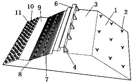
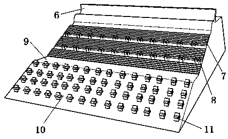
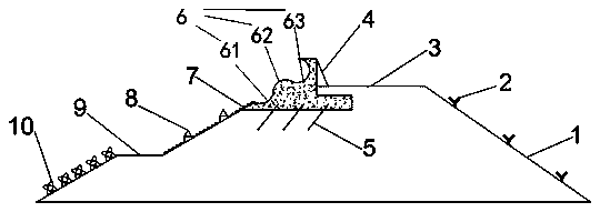
The invention discloses a seawall protective structure capable of high-efficiency combined energy dissipation. The backwater slope surface, the levee crown and the upstream slope surface successivelydefine a seawall protection structure body with the cross section being of a trapezoidal structure, the backwater slope surface and the upstream slope surface are located on the two sides of the leveecrown correspondingly, and the upstream slope surface is composed of wave walls, energy dissipation steps, an energy dissipation platform and an energy dissipation slope which are successively arranged from top to bottom. According to the seawall protective structure capable of high-efficiency combined energy dissipation, energy dissipation facilities of conventional seawall engineering are optimized, an energy dissipation step-wide tail pier-special shaped energy dissipation block combined energy dissipation form is provided, the energy dissipation efficiency of seawall engineering can be improved, the length of the upstream slope surface can be shortened, the engineering quantity is decreased, and the engineering cost is lowered; and the wave walls can prevent waves from overflowing a seawall, and the problem that waste caused by increasing the height of the seawall to prevent the waves from overflowing the seawall when the waves are high is solved.

Description

technical field [0001] The invention relates to the technical field of structural design for seawater flood prevention and / or tide prevention and disaster reduction, in particular to a seawall protection structure with high efficiency combined energy dissipation. Background technique [0002] Seawall is a kind of water-retaining structure built on land in ports, coasts and estuaries. Its main function is to protect coastal areas from tides and waves. At the same time, seawalls are also the main facilities of land reclamation projects. . [0003] In recent years, areas near the sea and rivers have been attacked more and more frequently by sea waves and river waves. Especially, the level of typhoons has been increasing year by year, which makes the requirements for seawall engineering anti-wind and wave capabilities higher and higher. Traditional seawall projects often adopt one or more structures of special-shaped energy-dissipating blocks, including fence panels, twisted bl...

Claims


Application Information

Patent Timeline
Patent Type & Authority Applications(China)
IPC IPC(8): E02B3/06
CPCE02B3/066Y02A10/11
Inventor 王桂生孙勇詹同涛沈继华秦小桥赵永刚屈学平韩福涛徐杰杨中彭光华陈长柏
Owner 中水淮河规划设计研究有限公司
Learn More