
A method and system for measuring the rotation angle of an aircraft

A technology of rotation angle and measurement method, which is applied in the field of measurement method and system of aircraft rotation angle, can solve the problems of difficult measurement, low precision, tooling falling off, etc., and achieve the effect of simple operation and accurate measurement results

Active Publication Date: 2020-10-13
新拓三维技术(深圳)有限公司
View PDF7 Cites 0 Cited by
  • Summary
  • Abstract
  • Description
  • Claims
  • Application Information

AI Technical Summary

Problems solved by technology

[0003] The measurement method of the protractor is cumbersome and complicated, with low precision, and it is difficult to measure when the rudder surface is non-planar
There are mainly two ways to fix the sensor on the rudder surface of the aircraft: binding and clamping. Either way, it is difficult to determine the spatial position relationship between the sensor measurement axis and the rudder surface rotation axis. At the same time, the tooling for fixing the sensor Installed on the rudder surface of the aircraft, there is a risk of damage to the rudder surface of the aircraft due to over-clamping, and the risk of tooling falling off due to under-clamping. When the rudder surface rotates, the clamping status of the tooling cannot be monitored in real time.
The measurable angle range of monocular vision is small, and the method of calculating the angle through the normal direction of the center of the feature circle has low precision
[0004] There is a lack of an accurate method and system for measuring the rotation angle of the aircraft in the prior art

Method used


Image

  • A method and system for measuring the rotation angle of an aircraft
  • A method and system for measuring the rotation angle of an aircraft
  • A method and system for measuring the rotation angle of an aircraft

Examples


Embodiment 1

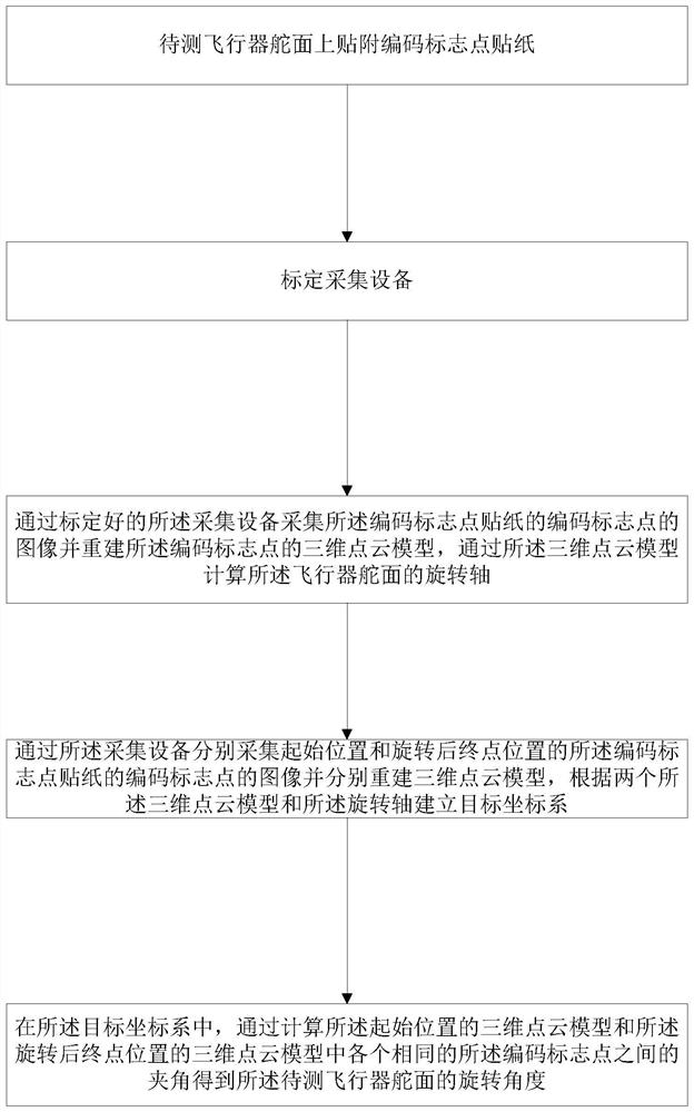
[0033] Such as figure 1 As shown, a method for measuring the rotation angle of an aircraft comprises the following steps:

[0034] S1: Attach coded mark point stickers on the rudder surface of the aircraft to be tested;

[0035] Coded marker points have unique feature information, and coded marker points include circular features and circular features. Through digital image processing technology, the coded feature points can be identified on the image, and the image coordinates of the coded feature points in the image can be calculated. In a specific embodiment, 5 different coded marker stickers are pasted, and it can be understood that more than 5 coded marker stickers can also be pasted.

[0036] S2: calibration acquisition equipment;

[0037] In one embodiment, the acquisition device includes two cameras. Place the calibration plate with coded points under the field of view of the camera, obtain camera images of the calibration plate at different positions and attitudes...

Embodiment 2

[0052] The invention provides a measurement system for the rotation angle of an aircraft, comprising: a collection unit and a processing unit, wherein the collection unit is used to collect the image data of the coded mark points on the coded mark point sticker; the processing unit is used to control the collection unit; The image data; calculate the angle of rotation of the rudder surface of the aircraft to be measured, and realize the method as described in Embodiment 1.

[0053] Such as Figure 4 As shown, in a specific embodiment, the acquisition unit includes a camera 1 and a camera 2, and also includes a control box 3, and the two cameras are respectively connected with the control box 3 to form an acquisition unit 5 together; the processing unit has a processing Capability of the computer 4, the control box 3 is connected with the computer 4. The processing unit controls the camera 1 and the camera 2 by sending instructions, and the image data collected by the camera 1...

Embodiment 3

[0063] The method of the present invention is illustrated below through a more specific example.

[0064] 1. Paste the coding mark point sticker 10 on the rudder surface 9 of the aircraft to be tested;

[0065] Such as Figure 7 As shown, five different coded marker stickers 10 are pasted on the surface of the rudder surface 9 of the aircraft to be tested.

[0066] Such as Figure 8(a) ~ Figure 8(c) As shown, the coded marker sticker 10 has feature information, and the feature information includes: circular features, ring features. The features can be identified by digital image processing technology, and the codes of the marker points can be obtained.

[0067] 2. Arranging and calibrating the collection equipment; in this embodiment, the collection equipment is two cameras and a measurement box; the processing unit is a computer.

[0068] Place the calibration plate with coded mark points in the field of view of the camera, adjust the focal length and aperture of the came...


PUM


Abstract

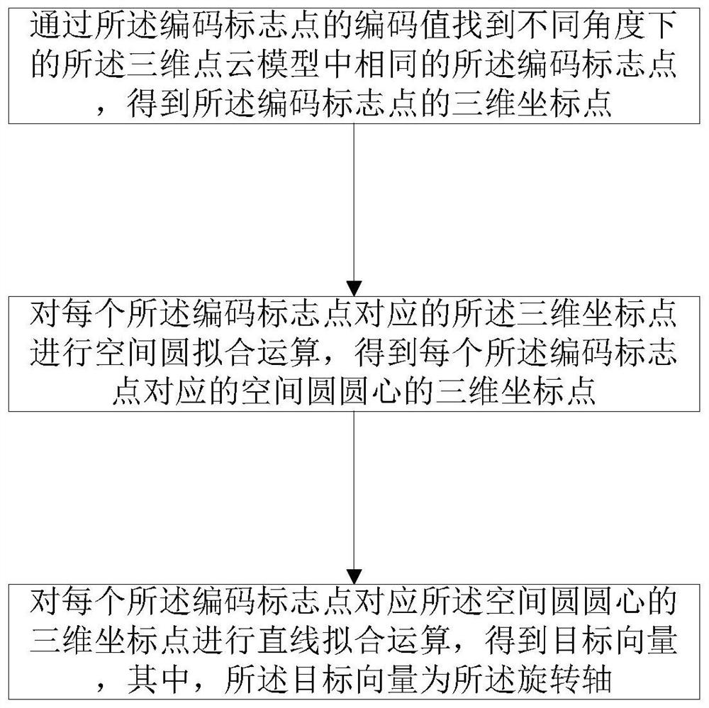
The invention provides a method and system for measuring the rotation angle of an aircraft. The method comprises: attaching a coded mark point paster on a to-be-measured aircraft control plane; calibrating a collection device; collecting an image of a coded mark point of the coded mark point paster by using a calibrated collection device and reconstructing a three-dimensional point cloud model ofthe coded mark point, and calculating a rotation angle of the aircraft control plane; respectively collecting images of the coded mark point of the coded mark point paster at a starting point and an end point position after rotation and reconstructing three-dimensional point cloud models respectively, and establishing a target coordinate system by combining the two three-dimensional point cloud models with the rotation shaft; and in the target coordinate system, calculating included angles between all same coded mark points in the three-dimensional point cloud model at the starting point and the three-dimensional point cloud model at the end point position after rotation to obtain a rotation angle of the to-be-measured aircraft control plane. Compared with the traditional manual measurement method, the provided method enables the aircraft control plane to be protected from being damaged mechanically. The method is operated simply; and the measuring result is accurate.

Description

technical field [0001] The invention relates to the technical field of test and measurement, in particular to a method and system for measuring the rotation angle of an aircraft. Background technique [0002] The aircraft rudder angle measurement is an important test item in the aircraft ground assembly test. The comparison between the rotation angle of the aircraft rudder surface issued by the control command and the actual rotation angle of the rudder surface can be used to test the relationship between the aircraft electronic control system and the mechanical transmission system. Whether the matching is qualified. At present, there are mainly three measurement schemes in the field of aircraft rotation angle measurement: 1. A measurement method based on a protractor; 2. A measurement method based on an inclination sensor; 3. A measurement method based on a monocular vision system. The measurement method based on the protractor is to obtain the rotation angle of the rudder...

Claims


Application Information

Patent Timeline
Patent Type & Authority Patents(China)
IPC IPC(8): G01B11/26
CPCG01B11/26
Inventor 李磊刚王祺蒋召玉庞然拜宏伟
Owner 新拓三维技术(深圳)有限公司
Learn More