Magnetic resonance coil position determination method and device, and magnetic resonance imaging system

A coil position and determination method technology, applied in magnetic resonance measurement, measuring devices, measuring magnetic variables, etc., can solve the problems of magnetic resonance signal interference of markers, error-prone, and influence on the correct selection of coils, etc., to improve accuracy and Accuracy, the effect of solving signal distortion and loss

Active Publication Date: 2019-08-06
SHANGHAI NEUSOFT MEDICAL TECH LTD +1
View PDF10 Cites 3 Cited by
  • Summary
  • Abstract
  • Description
  • Claims
  • Application Information

AI Technical Summary

Problems solved by technology

The determination of the coil position is the basis for the correct selection of the coil. If the coil position identification is not accurate, it will affect the correct selection of the coil, and then affect the image quality.
[0004] In the related art, the method of adding markers to the coil is usually used to identify the position of the coil. This identification method is slow in recognition speed and error-prone, and the markers are likely to interfere with the magnetic resonance signal.

Method used


Image

  • Magnetic resonance coil position determination method and device, and magnetic resonance imaging system
  • Magnetic resonance coil position determination method and device, and magnetic resonance imaging system
  • Magnetic resonance coil position determination method and device, and magnetic resonance imaging system

Examples


Embodiment Construction

[0040] Reference will now be made in detail to the exemplary embodiments, examples of which are illustrated in the accompanying drawings. When the following description refers to the accompanying drawings, the same numerals in different drawings refer to the same or similar elements unless otherwise indicated. The implementations described in the following exemplary examples do not represent all implementations consistent with the present disclosure. Rather, they are merely examples of apparatuses and methods consistent with aspects of the present disclosure as recited in the appended claims.

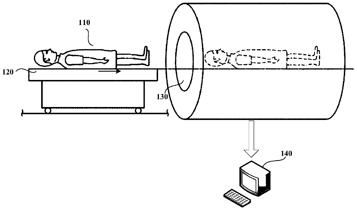
[0041] see figure 1 , which simply shows the structure diagram of the MRI system. Such as figure 1 As shown, when the patient 110 is doing an MRI scan, the patient 110 lies supine or prone on the scanning bed 120, and the scanning bed 120 can be moved along the figure 1 Move in the direction of the arrow in , so that the scanning bed 120 drives the patient 110 into the cavity 130 fo...


PUM


Abstract

The invention discloses a magnetic resonance coil position determination method and device, and a magnetic resonance imaging system. The method comprises the following steps of collecting magnetic resonance signals received by a coil in pre-scanning and determining projection data of the coil; determining an initial center of gravity position of the coil according to the projection data and a corresponding gradient distortion correction factor; calculating an offset of the initial center of gravity position relative to a physical center of gravity of the coil according to a physical structuralparameter of the coil and a coil channel receiving the magnetic resonance signals in the coil; and migrating the initial center of gravity position for the offset to obtain the physical center of gravity position of the coil. In the invention, a calculation speed is fast, and interferences of a marker on the magnetic resonance signals are avoided; and a calculation deviation caused by signal distortion losses and the like when the coil is at an imaging edge is solved, and accuracy of coil positioning is improved.

Description

technical field [0001] The present disclosure relates to the technical field of magnetic resonance imaging, and in particular to a method, a device and a magnetic resonance imaging system for determining the position of a magnetic resonance coil. Background technique [0002] Magnetic Resonance Imaging (MRI) is one of the main imaging methods of modern medical imaging. The basic principle of magnetic resonance imaging is based on the phenomenon of magnetic resonance, using radio frequency to excite hydrogen protons in the human body, using gradient fields to encode positions, and using receiving coils to receive electromagnetic signals containing position information, and finally using Fourier transform to reconstruct image information . [0003] In magnetic resonance imaging, in order to obtain a higher signal-to-noise ratio, it is necessary to place the coil as close as possible to the imaging area. Therefore, it is very important to correctly select the coils for receiv...

Claims


Application Information

Patent Timeline
Patent Type & Authority Applications(China)
IPC IPC(8): G01R33/36A61B5/055
CPCA61B5/055G01R33/3621
Inventor 蒋先旺伍亚军
Owner SHANGHAI NEUSOFT MEDICAL TECH LTD
Why Eureka
Try Eureka