A control method and device for an automatic control device

A control method and equipment technology, applied in sequence/logic controller program control, electrical program control and other directions, can solve problems such as large error of visible light information, easy occurrence of dangerous accidents, affecting the working performance of automatic control equipment, etc.

Active Publication Date: 2020-09-15
SUZHOU EAVISION ROBOTIC TECH CO LTD
View PDF11 Cites 0 Cited by
  • Summary
  • Abstract
  • Description
  • Claims
  • Application Information

AI Technical Summary

Problems solved by technology

However, it has been found in practice that when the environment where the automatic control equipment is located is insufficiently lighted (that is, the light intensity of the environment where the automatic control equipment is located does not meet the working conditions of the vision device), the visible light information obtained by the visual device based on visible light is incorrect. At this time, the automatic control equipment still performs corresponding operations based on the visible light information, which affects the performance of the automatic control equipment and is prone to dangerous accidents

Method used


Image

  • A control method and device for an automatic control device
  • A control method and device for an automatic control device
  • A control method and device for an automatic control device

Examples


Embodiment 1

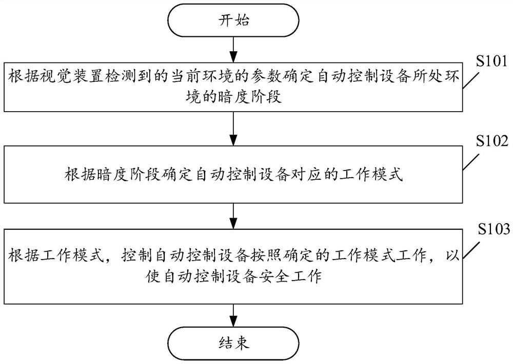
[0079] see figure 1 , figure 1 It is a schematic flowchart of a control method for an automatic control device provided by an embodiment of the present invention. Among them, such as figure 1 As shown, the control method of the automatic control device may include the following steps:

[0080] S101. Determine the darkness stage of the environment where the automatic control device is located according to the parameters of the current environment detected by the vision device.

[0081] In the embodiment of the present application, the dark stage may be a dark stage or a bright stage, which is not limited in this embodiment.

[0082] In the embodiment of the present application, the automatic control device may be an unmanned agricultural machine, an unmanned aerial vehicle, an unmanned driving device, etc., which is not limited in this embodiment.

[0083] In the embodiment of this application, the darkness stage can be pre-configured and stored, and the preset darkness sta...

Embodiment 2

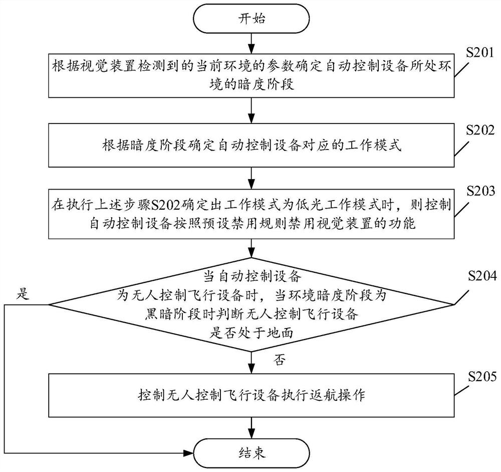
[0112] see figure 2 , figure 2 It is a schematic flowchart of a control method for an automatic control device provided by an embodiment of the present invention. Among them, such as figure 2 As shown, the control method of the automatic control device may include the following steps:

[0113] S201. Determine the darkness stage of the environment where the automatic control device is located according to the parameters of the current environment detected by the vision device.

[0114] In the embodiment of the present application, the dark stage is one of a dark stage, a bright stage, and a low light stage.

[0115] As a further optional implementation manner, determining the darkness stage of the environment where the automatic control device is located according to the parameters of the current environment detected by the visual device may include the following steps:

[0116] judging whether the ambient light intensity detected by the visual device is less than a pres...

Embodiment 3

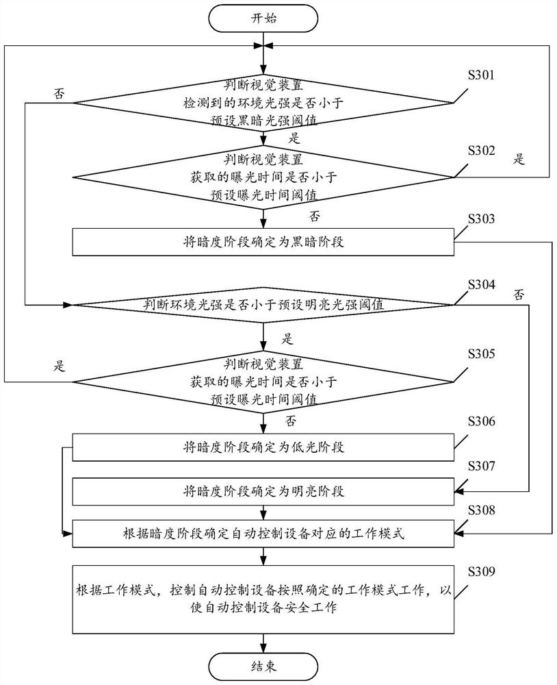
[0162] see image 3 , image 3 It is a schematic flowchart of a control method for an automatic control device provided by an embodiment of the present invention. Among them, such as image 3 As shown, the control equipment of the automatic control equipment may include the following steps:

[0163] S301. Determine whether the ambient light intensity detected by the vision device is less than a preset dark light intensity threshold, if less, perform step S302; if not, perform step S304.

[0164] In the embodiment of the present application, the parameters include the ambient light intensity of the environment where the automatic control device is currently located and the exposure time acquired by the vision device.

[0165] In the embodiment of the present application, each darkness stage has a corresponding light intensity threshold interval. The automatic control device can determine the darkness stage of the environment where the automatic control device is currently l...


PUM


Abstract

A control method of an automatic control device and a device are disclosed. The automatic control device is provided with a visual device based on visible light. The method comprises the following steps of determining a darkness phase of an environment where the automatic control device is located according to current environment parameters detected by the visual device; determining a working modecorresponding to the automatic control device according to the darkness phase; and according to the working mode, making the automatic control device work according to the determined working mode sothat the automatic control device can fly safely. By using the control method of the automatic control device and the device, the automatic control device can automatically adjust a working state according to ambient light intensity, an influence of the ambient light intensity on the working performance of the automatic control device is avoided and then a dangerous accident is avoided too.

Description

technical field [0001] The invention relates to the technical field of automatic control, in particular to a control method and device for automatic control equipment. Background technique [0002] With the continuous development of automatic control equipment technology, the application fields of automatic control equipment are becoming more and more extensive. Nowadays, some automatic control equipment is equipped with visual devices based on visible light (such as visible light cameras, stereo vision devices, radar, etc.) to perceive the environment around the automatic control equipment. At this time, the visual devices based on visible light need to work under the condition of visible light . However, it is found in practice that when the environment where the automatic control equipment is located has insufficient light (that is, the light intensity of the environment where the automatic control equipment is located does not meet the working conditions of the vision d...

Claims


Application Information

Patent Timeline
Patent Type & Authority Patents(China)
IPC IPC(8): G05B19/04
CPCG05B19/04
Inventor 卡米尔·梅森黄继华但汉曙
Owner SUZHOU EAVISION ROBOTIC TECH CO LTD
Why Eureka
Try Eureka