
Battery pack

A technology of battery pack and bottom plate, which is applied in the direction of batteries, battery pack parts, secondary batteries, etc.

Active Publication Date: 2019-08-06
HONDA MOTOR CO LTD
View PDF18 Cites 0 Cited by
  • Summary
  • Abstract
  • Description
  • Claims
  • Application Information

AI Technical Summary

Problems solved by technology

[0008] In recent years, in order to improve work efficiency, there has been an increasing tendency to increase the capacity of battery packs mounted on electric lawn mowers, and this has created a need to solve the problem of heat generated from the battery unit

Method used


Image

  • Battery pack
  • Battery pack
  • Battery pack

Examples


Embodiment Construction

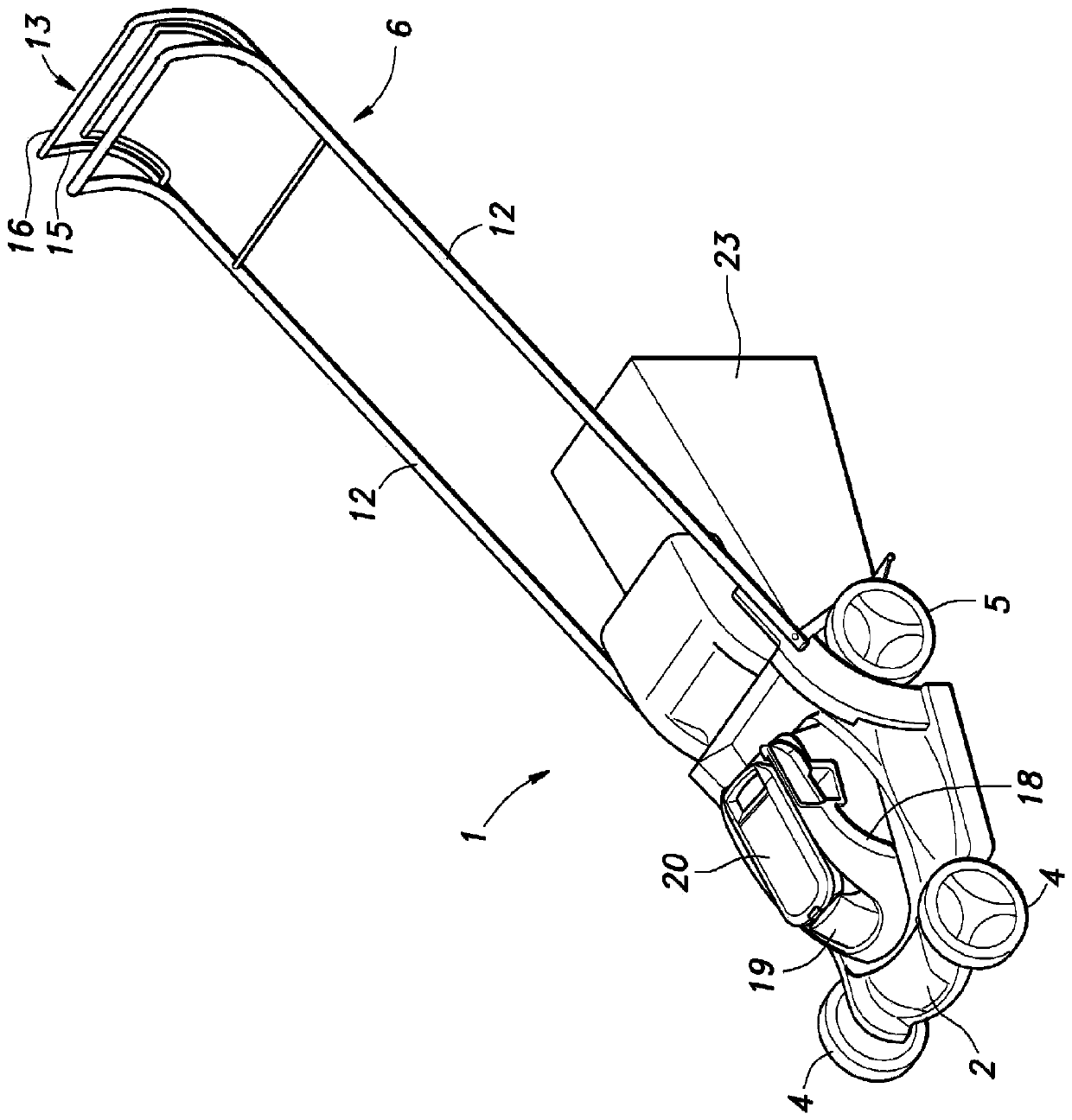
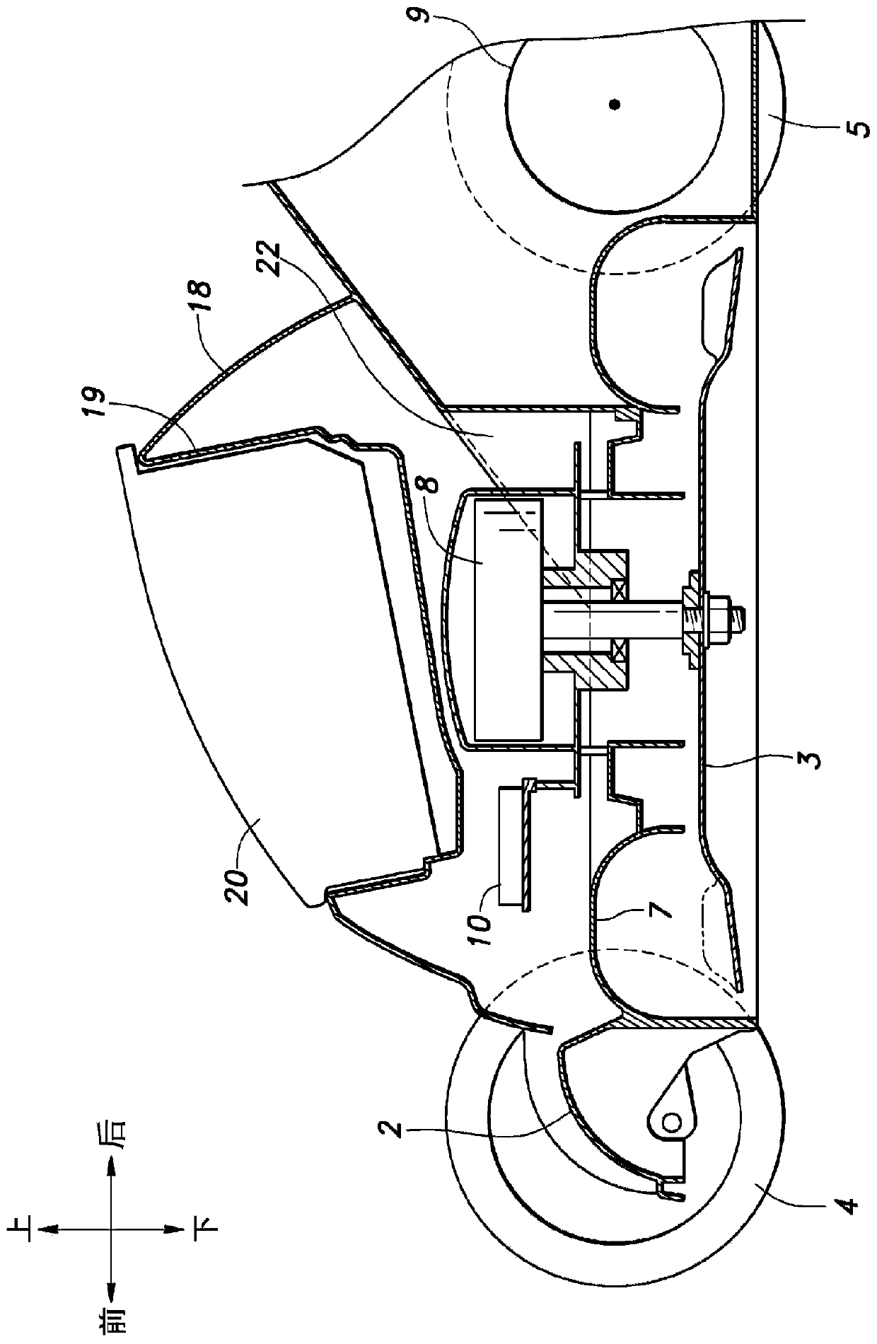
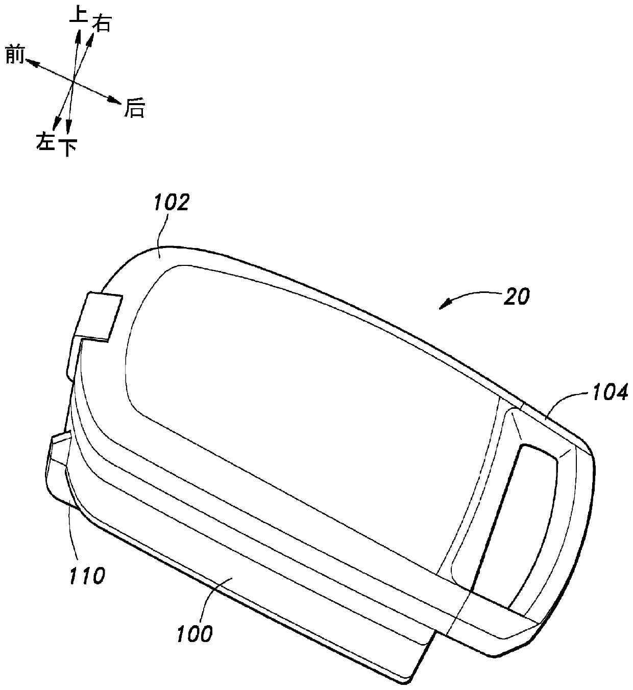
[0040] A battery pack according to a preferred embodiment of the present invention mounted on an electric lawn mower as an example of an electric working machine is referred to below Figure 1 to Figure 7 to describe.

[0041] Such as figure 1 and figure 2 As shown, the electric lawnmower 1 according to the present embodiment includes: a main body 2; a blade 3 disposed in a lower portion of the main body 2; and a pair of front wheels 4 and a pair of rear wheels coupled to the main body 2; and a handle 6, which extends backward and upward from the main body 2. A cavity 7 is provided centrally in the lower part of the body 2 and the blade 3 is received in the cavity 7 . The main body 2 supports a blade motor 8 having a rotating shaft cooperating with the blade 3 , and a travel motor 9 for driving the left and right rear wheels 5 . Both the blade motor 8 and the travel motor 9 are constituted by electric motors, and the main body 2 is provided with a control unit 10 for driv...


PUM


Abstract

To provide a battery pack having an air flow passage extending from the exterior of the battery pack to a battery cell so that water is prevented from reaching the battery cell. This battery pack 20 has a housing 100 having an outer bottom plate 145 and an inner bottom plate 141, the housing defining a main chamber for accommodating a battery cell 98 above the inner bottom plate, while defining anauxiliary chamber between the outer bottom plate and the inner bottom plate. The outer bottom plate includes an outer flat plate section 146 formed approximately parallel to the inner bottom plate, and an ascending wall 147 extending from the end portion of the outer flat plate section and reaching the end portion of the inner bottom plate. The inner bottom plate is provided with at least one opening having a cylindrical flange protruding toward the outer bottom plate. In the housing, an air flow passage A is formed, whereby the exterior of the housing and the auxiliary chamber communicate. At a position that is adjacent to the ascending wall, the bottom surface of the inner bottom plate slopes upward toward the ascending wall relative to a reference plane 144 of the bottom surface of theinner bottom plate, away from the outer bottom plate. The air flow passage includes a first flow passage hole 149 having an edge portion on a higher side than the reference plane of the inner bottomplate.

Description

technical field [0001] The present invention relates to a removable, rechargeable battery pack for powering an electric lawn mower. Background technique [0002] Electric work machines for mowing lawns, such as electric lawn mowers, are known to be equipped with removable battery packs to increase user productivity. For example, see Patent Document 1. Since such electric work machines are primarily used outdoors, there is a need to protect the battery pack and associated electrical components from moisture from rain and watering devices. [0003] The electric lawn mower disclosed in Patent Document 1 is provided with a battery cover configured to selectively close a battery mounting portion, thereby protecting the battery mounting portion from moisture. In addition, a drain hole is provided in the lowermost part of the battery mounting portion, so that moisture (such as rainwater) that may enter the battery cover can be drained from the drain hole, and waterproofness of th...

Claims


Application Information

Patent Timeline
Patent Type & Authority Applications(China)
IPC IPC(8): H01M2/10B25F5/00H01M10/613H01M10/6235H01M10/6561H01M50/204
CPCH01M10/613H01M10/6235H01M10/6556H01M10/6554H01M10/6566H01M10/6563H01M10/6565B25F5/02Y02E60/10H01M50/204H01M10/625H01M10/6561A01D34/6806A01D34/69A01D34/78A01D2101/00B25F5/00H01M2220/20H01M50/24
Inventor 末吉俊一郎村冈敬介永谷修志
Owner HONDA MOTOR CO LTD
Learn More