Reinforced concrete I beam construction template and operation method thereof
A technology of reinforced concrete and I-beams, applied in the direction of manufacturing tools, mold fixtures, mold auxiliary parts, etc., can solve the problems of wasting time, troublesome installation, etc., and achieve the effect of easy disassembly and installation and time saving
- Summary
- Abstract
- Description
- Claims
- Application Information
AI Technical Summary
Problems solved by technology
Method used
Image
Examples
Embodiment 1
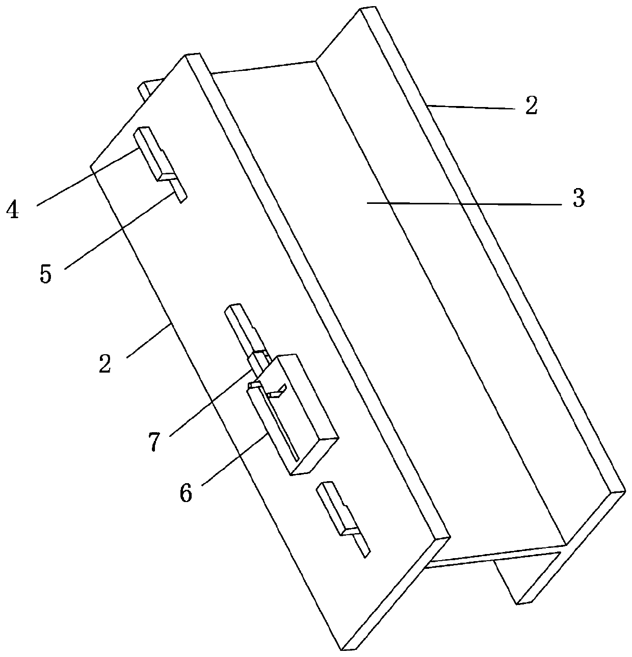
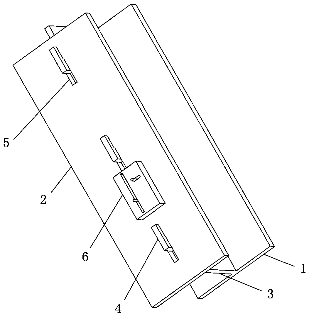
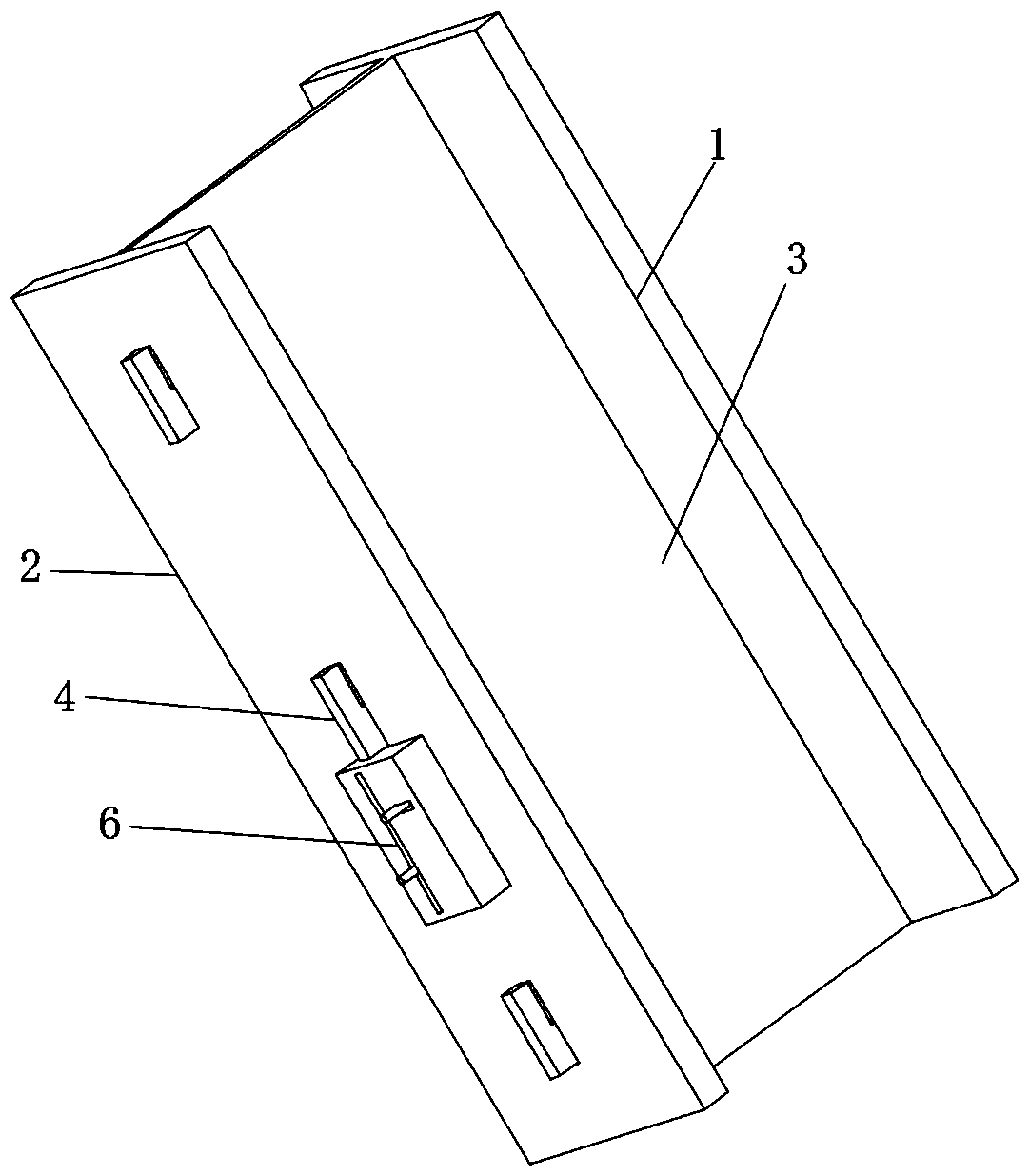
[0029] Reference Figure 1-4 , A reinforced concrete I-beam construction template, comprising an upper baffle 1, a lower baffle 2 and a web 3, the upper baffle 1 and the web 3 are perpendicular to each other and are integrally formed, and the web 3 is away from the end of the upper baffle 1 Connected with a clamping block 4, the side wall of the lower baffle 2 is excavated with a clamping slot 5 that matches the clamping block 4, the web 3 is slidably connected to the lower baffle 2 through the clamping block 4, and the side wall of the lower baffle 2 is connected with The fastening box 6, the inside of the fastening box 6 is excavated with a first slide groove 10 parallel to the card groove 5, a locking block 7 is slidably connected to the first slide groove 10, and the locking block 7 is placed in the first slide groove 10 A first spring 11 is connected between one end and the wall of the first chute 10, and a limit component is connected inside the fastening box 6. Before pou...
Embodiment 2
[0031] Reference Figure 5 , A reinforced concrete I-beam construction template, which is basically the same as embodiment 1, except that a second chute 9 perpendicular to the first chute 10 is excavated inside the fastening box 6, and the first chute 10 communicates with the second chute 9.
[0032] The limiting component includes a limiting block 8 and a second spring 12. The limiting block 8 is slidably connected in the second sliding groove 9, and the second spring 12 is connected to the limiting block 8 and one end of the second sliding groove 9 is connected to the second Between the chute 9 groove walls.
[0033] When the locking block 7 is pulled, the locking block 7 pushes up the limit block 8 and slides upward in the second chute 9. When the locking block 7 and the clamping block 4 resist, the limit block 8 is subjected to the force of the second spring 12 The reset blocks the locking block 7 to prevent it from sliding back. When the module needs to be disassembled, pull ...
Embodiment 3
[0035] Reference Figure 4 , A reinforced concrete I-beam construction template, which is basically the same as Embodiment 2. Furthermore, the clamping block 4 is L-shaped, and the L-shaped clamping block 4 facilitates the sliding and dislocation clamping of the clamping block 4 and the clamping slot 5.
PUM
 Abstract
Description
Claims
Application Information
 - R&D
- Intellectual Property
- Life Sciences
- Materials
- Tech Scout
- Unparalleled Data Quality
- Higher Quality Content
- 60% Fewer Hallucinations
Browse by: Latest US Patents, China's latest patents, Technical Efficacy Thesaurus, Application Domain, Technology Topic, Popular Technical Reports.
© 2025 PatSnap. All rights reserved.Legal|Privacy policy|Modern Slavery Act Transparency Statement|Sitemap|About US| Contact US: help@patsnap.com


