A wireless charging system for electric vehicles
A technology of wireless charging and electric vehicles, applied in the direction of electric vehicle charging technology, electric vehicles, charging stations, etc., can solve the problems of low wireless charging efficiency, inapplicability of fast charging, etc., and achieve the effect of strong applicability
- Summary
- Abstract
- Description
- Claims
- Application Information
AI Technical Summary
Problems solved by technology
Method used
Image
Examples
Embodiment 1
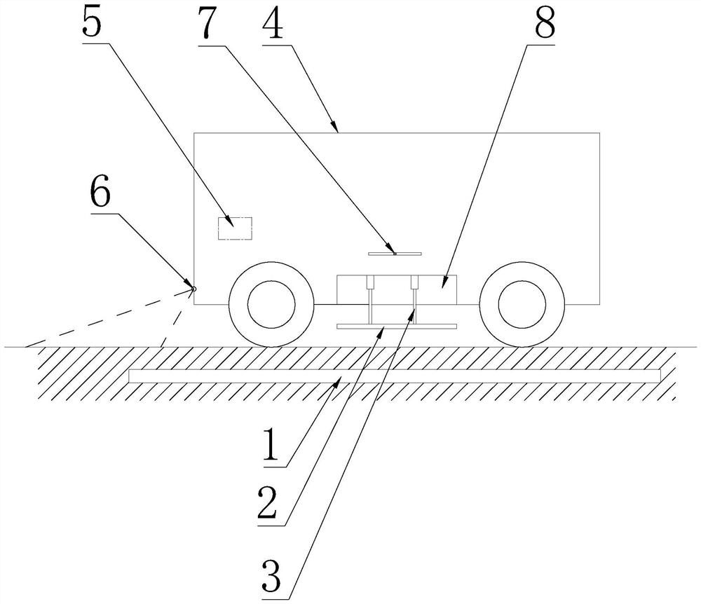
[0023] The invention provides a wireless charging system for electric vehicles, such as figure 1 As shown, it includes a charger 1 pre-buried in the roadbed and a receiver 2 installed on the chassis of the vehicle 4, and the receiver 2 and the charger 1 are mutually adapted so that the vehicle 4 drives the vehicle on the chassis of the vehicle 4. When the receiver 2 moves above the charger 1 , the charger 1 is turned on and charges the receiver 2 through wireless charging technology, and the receiver 2 is electrically connected to the storage battery or the battery pack inside the vehicle 4 . The aforementioned adaptation of the receiver 2 to the charger 1 means that the receiver 2 and the charger 1 can effectively transmit electric energy wirelessly when the charger 1 is turned on.
Embodiment 2
[0025] Its structure is basically the same as that of Embodiment 1, the difference is that: the chassis of the vehicle is provided with an accommodating cavity 8 for accommodating the receiver 2, and a lifting mechanism 3 is provided in the accommodating cavity 8, taking the lifting cylinder as an example, the described The receiver 2 is installed on the piston rod of the lift cylinder, so that the receiver 2 is driven to be stored in the accommodation cavity 8 or moved vertically downwards to the road below the chassis of the vehicle 4 through the piston rod of the lift cylinder. Reducing the distance between the receiver 2 on the vehicle 4 and the charger 1 under the roadbed through the lifting mechanism 3 can make the electrical gap between the receiver 2 and the charger 1 small, so the loss in the wireless charging process is small, and the charging process more efficient.
[0026] As an improvement, the lifting cylinder can use a motor to drive the screw lift, that is, th...
Embodiment 3
[0028] Its structure is basically the same as that of the second embodiment, except that the wireless charging system further includes a control module 5 integrated into the central control computer of the vehicle 4 . The control module 5 is electrically connected to the driver of the lifting mechanism 3. Taking the electrically driven screw lift as an example, the motor of the screw lift is electrically connected to the control module 5, thus giving a control command through the control module 5, so The lifting mechanism 3 performs corresponding lifting action or static locking according to the control command. As a preference, factors such as the speed and stroke of the lifting action of the lifting mechanism 3, and the combined actions formed by different speeds and strokes can be completed by corresponding control instructions. It is up to you to determine which specific control instructions are suitable for different application scenarios. Not listed one by one.
PUM
 Abstract
Description
Claims
Application Information
 - R&D
- Intellectual Property
- Life Sciences
- Materials
- Tech Scout
- Unparalleled Data Quality
- Higher Quality Content
- 60% Fewer Hallucinations
Browse by: Latest US Patents, China's latest patents, Technical Efficacy Thesaurus, Application Domain, Technology Topic, Popular Technical Reports.
© 2025 PatSnap. All rights reserved.Legal|Privacy policy|Modern Slavery Act Transparency Statement|Sitemap|About US| Contact US: help@patsnap.com

