A hydraulic compaction method for backfilling bridge and culvert abutments

A bridge and culvert, hydraulic technology, applied in soil protection, construction, infrastructure engineering and other directions, can solve the problems of increasing construction costs, low compaction quality, slow construction progress, etc., to save construction costs, ensure compaction quality, The effect of reducing the amount of construction

Active Publication Date: 2020-10-02
CHINA MCC17 GRP
View PDF2 Cites 0 Cited by
  • Summary
  • Abstract
  • Description
  • Claims
  • Application Information

AI Technical Summary

Problems solved by technology

[0002] At present, during the backfill construction of the bridge and culvert abutment, due to the influence of the narrow working face and the safety distance from the structure, the vibratory roller is not in place, and the dynamic compaction machine has a great impact on the structure, and the compaction near the structure is not good. If it is in place, there will be an enlarged space for tamping. At the same time, the traditional tamping machine is likely to cause interlayer slippage and separation caused by layered compaction, resulting in low tamping quality, slow construction progress, and increased construction costs. question

Method used


Image

  • A hydraulic compaction method for backfilling bridge and culvert abutments
  • A hydraulic compaction method for backfilling bridge and culvert abutments

Examples


Embodiment 1

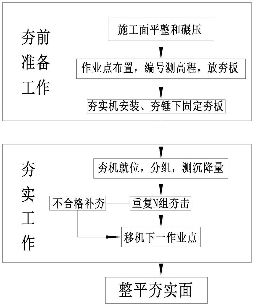
[0031] Such as figure 1 As shown, the present invention selects sandy soil and fine-grained soil backfill layer, including the following steps:

[0032] Step 1. Preparation before ramming:

[0033] A1. The construction surface must be leveled with a bulldozer before ramming, and then the road roller is rolled, and the compaction standards and flatness required by the design are inspected. For the construction surface that does not meet the design requirements, repeat leveling and rolling until it meets the design It is required that when the construction surface is relatively dry, an appropriate amount of water should be sprayed to prevent the surface from dusting, which will affect the energy transfer to the deep layer;

[0034] A2. Release the operating points on the construction surface after the inspection is passed. When arranging the operating points, the gap-type operating points are arranged. The gap-type operating points are arranged at 20cm apart from the edge of each opera...

Embodiment 2

[0045] The difference from Example 1 is that when selecting the backfill layer of gravel-grained soil, due to the small deformation of gravel-grained soil, the gap-type arrangement of operating points in step A2 is 30cm apart from the edge of each operating point, and is arranged in an equilateral triangle. , The distance between the working point near the back of the platform and the back of the platform is 50cm; in step B1, repeat 5 sets, in step B2, when the relative settlement difference between the 5th and 4th sets is less than 10mm, stop the point The measured compaction coefficient within a depth of 1m below the construction surface is 0.94, and the K30 value is 134Mpa / m.

Embodiment 3

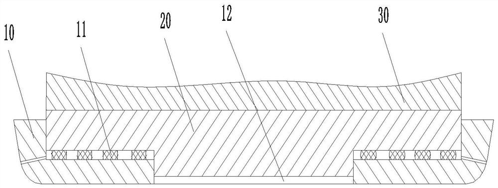
[0047] Such as figure 2 As shown, on the basis of embodiment 1, the following improvements are made: the ram plate includes a first ram plate 10 and a second ram plate 20, the first ram plate 10 is a truncated cone-shaped structure, and the middle of the first ram plate 10 is provided with The stepped hole 12, the buffer pad 11 on the stepped surface of the stepped hole 12, the cross section of the second ram plate 20 is T-shaped, the second ram plate 20 is sleeved in the stepped hole 12, the top surface of the second ram plate 20 and the ram 30 The thickness of the fixedly connected second ram plate 20 is equal to the sum of the thickness of the first ram plate 10 and the amount of deformation of the cushion 11. When the rammer strikes, the second ram plate 20 first moves downwards, and the second ram plate 20 then transmits the force to the first ram plate 10 through the cushion 11, and the first ram plate 10 undergoes a deformation process in the cushion 11 The force recei...


PUM


Abstract

The invention discloses a method for performing backfilling and hydraulic compaction on the stage back of bridges and culverts, and belongs to the technical field of backfilling construction of the stage back of the bridges and culverts. The method for performing backfilling and hydraulic compaction on the stage back of the bridges and culverts comprises the following steps that step 1, preparingwork before tamping is carried out; specifically, A1, a construction surface is leveled and rolled; A2, operation point layout is carried out, numbering and elevation measurement are carried out; A3,a rammer compactor is installed, a compaction plate is fixed to the lower part of a rammer; step 2, compaction work is carried out; specifically, B1, the rammer compactor is in place, every three hammers are taken as a group, and the settlement of each group is measured; B2, N groups of compaction is repeated; and B3, a machine is moved to the next operation point; step 3, the compaction surface is leveled after all the compaction points are rammed; and step 4, quality inspection is carried out. Compared with the traditional dynamic compaction technology, the method for performing backfillingand hydraulic compaction on the stage back of the bridges and culverts is small in an acting force peak value, high in striking frequency, soft in action and not prone to shearing a filling layer streamline; compared with vibration compaction technology, the compaction energy is high, penetration ability is high and uniform, impact depth is large, and relatively uniform compactness can be obtainedin a larger depth range. The method for performing backfilling and hydraulic compaction on the stage back of the bridges and culverts has the advantages of high strength, high efficiency, low energyconsumption, low noise, energy conservation and environmental protection.

Description

Technical field [0001] The invention belongs to the technical field of backfill construction of the back of bridge and culvert abutments, and particularly relates to a method for hydraulic tamping of backfill of back of bridge and culvert abutments. Background technique [0002] At present, in the process of backfilling the back of bridges and culverts, due to the influence of the narrow working surface and the safety distance from the structure, the use of vibratory rollers is not in place, and the dynamic compaction machinery has a greater impact on the structure, and the vicinity of the structure is not compacted. When it is in place, there will be an enlarged space that cannot be tamped. At the same time, traditional tamping machines are likely to cause real-time layer slip and separation caused by layering, resulting in low tamping quality, slow construction progress, and increased construction costs, etc. problem. Summary of the invention [0003] The present invention aims...

Claims


Application Information

Patent Timeline
Patent Type & Authority Patents(China)
IPC IPC(8): E02D3/046
CPCE02D3/046
Inventor 肖来兵陈宇华陶家长
Owner CHINA MCC17 GRP
Why Eureka
Try Eureka