Circular steel ball worm gear structure and speed reducer provided with same

A technology of worm gear and reducer, applied in mechanical equipment, gear transmission, belt/chain/gear, etc., can solve the problems of complex worm gear structure, high friction and heat generation, low transmission efficiency, etc., to achieve low cost and friction heat. Small, less wear-resistant effect

Pending Publication Date: 2019-08-09
石雅 +1
View PDF5 Cites 2 Cited by
  • Summary
  • Abstract
  • Description
  • Claims
  • Application Information

AI Technical Summary

Problems solved by technology

[0005] However, there are still the following problems: low transmission efficiency, high friction and heat, easy to wear, etc., and the addition of a clearance elimination mechanism makes the structure of the worm gear complicated, the efficiency is reduced, and the cost is increased

Method used


Image

  • Circular steel ball worm gear structure and speed reducer provided with same
  • Circular steel ball worm gear structure and speed reducer provided with same
  • Circular steel ball worm gear structure and speed reducer provided with same

Examples


Embodiment 1

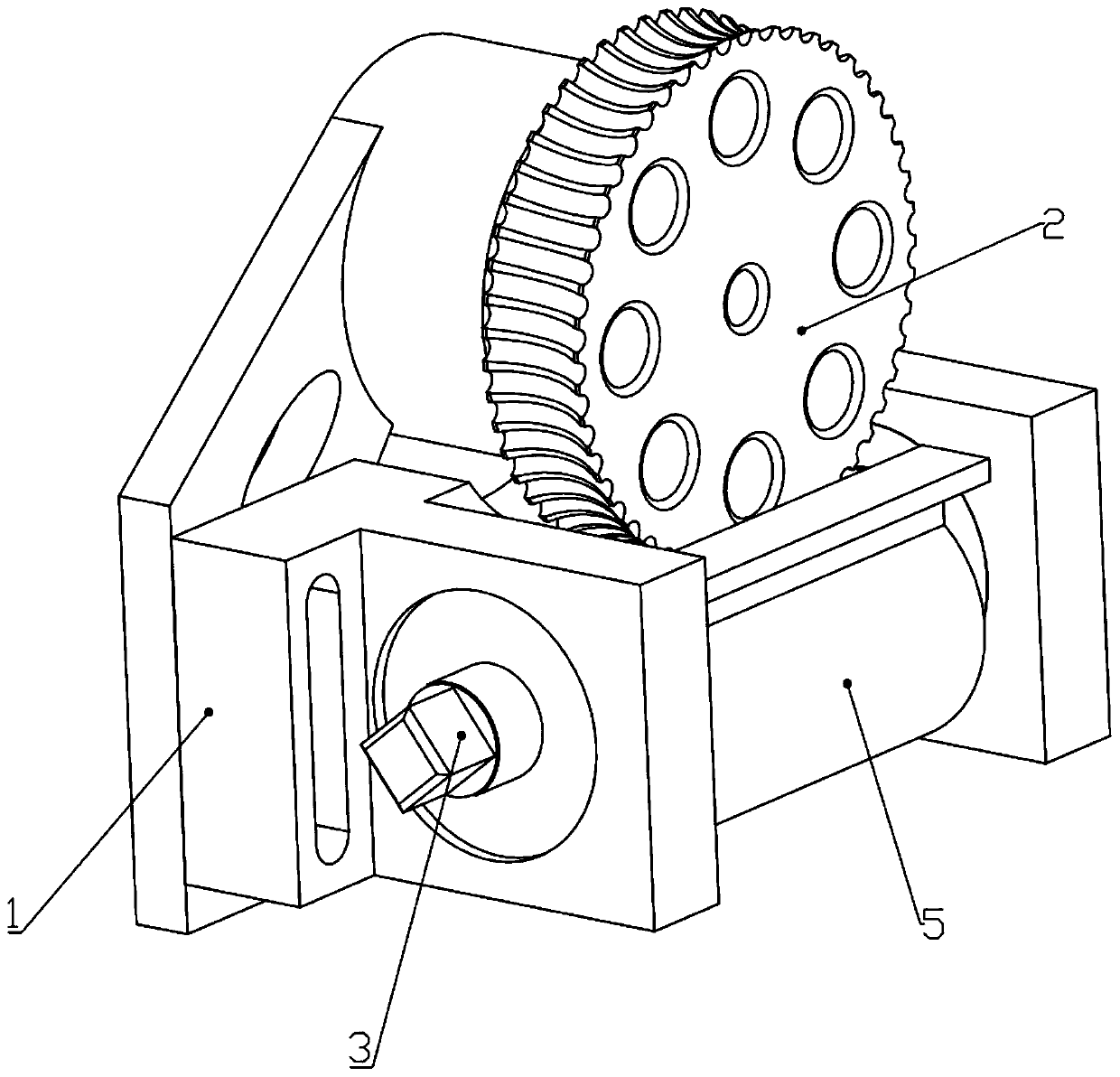
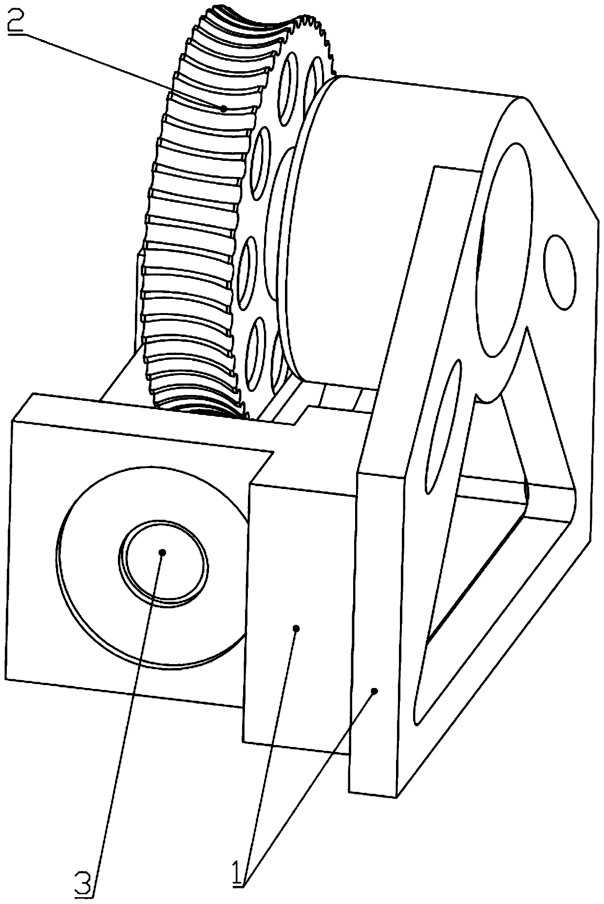
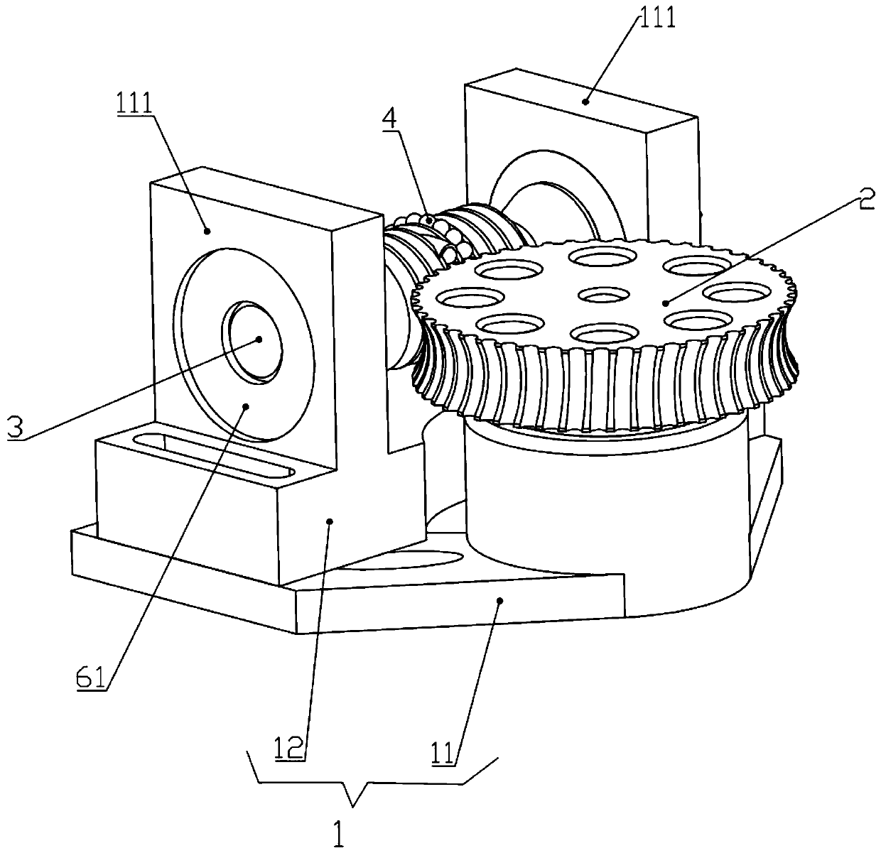
[0034] Such as Figures 1 to 7 As shown, a circulating steel ball worm gear structure includes a base 1, a turbine 2 and a worm 3; the turbine 2 and the worm 3 are both rotatably connected to the base 1;

[0035] The spiral groove 31 of the worm 3 is arc-shaped; the spiral groove 31 is provided with two inlets and outlets 32 for the balls 4 to enter and exit, and the two inlets and outlets 32 are respectively connected to the circulation pipe 33 arranged inside the worm 3 The two ends of the worm screw 3 are connected; the outer side of the extension direction of the worm 3 is provided with a retainer 5; the grooves 22 between the teeth 21 of the worm gear 2 are arc-shaped;

[0036] The balls 4 arranged in sequence are placed in the spiral groove 31 between the two inlets and outlets 32 and in the circulation pipe 33 , and the balls 4 can be moved along the two inlets and outlets 32 . The spiral groove 31 and the circulation pipe 33 circulate; a part of the balls 4 in the spi...

Embodiment 2

[0039] Such as Figures 1 to 7 As shown, a circulating steel ball worm gear structure includes a base 1, a turbine 2 and a worm 3; the turbine 2 and the worm 3 are both rotatably connected to the base 1;

[0040] The base mentioned here is mainly used to fix the position of the turbine 2 and the worm 3, so that the turbine 2 and the worm 3 can be directly or indirectly matched for transmission, and is also used for the installation and fixing of the circulating steel ball turbine and worm structure of the present invention, such as being installed and fixed on in the reducer.

[0041] The spiral groove 31 of the worm 3 is in the shape of an arc; this can form a good contact fit with the ball 4, and keep (limit) the ball 4 in the spiral groove 31, so that the ball 4 can roll or circulate along the spiral groove 31. Displacement. The spiral groove 31 is provided with two inlets and outlets 32 for the balls 4 to go in and out, and the two inlets and outlets 32 communicate with t...


PUM


Abstract

The invention discloses a circulating steel ball worm gear structure. The structure comprises a base, a worm gear and a worm; both the worm gear and the worm are rotationally connected with the base;a spiral groove of the worm is in a circular arc shape; and the spiral groove is provided with two inlets / outlets allowing balls to enter and exit from therein. The two inlets / outlets communicate withthe two ends of a circulating pipeline disposed inside the worm correspondingly; a retainer is arranged on the outer side of the worm in the extending direction; grooves between all teeth of the wormgear are each in a circular arc shape; the balls are arranged in the position, between the two inlets / outlets, in the spiral groove and in the circulating pipeline in sequence, and the balls can circulate along the position, between the two inlets / outlets, in the spiral groove and the circulating pipeline; part of the balls in the position, between the two inlets / outlets, in the spiral groove aredefined in the spiral groove by the inner side wall of the retainer, and the other part of the balls are defined in the spiral groove by the grooves; and the worm gear, the balls and the worm are incooperative transmission. The circulating steel ball worm gear structure is simple in structure, convenient to use, high in transmission efficiency, small in friction heating, not prone to abrasion and low in cost.

Description

technical field [0001] The invention relates to the field of technical equipment, in particular to a circulating steel ball worm structure and a reducer with the structure. Background technique [0002] Worm gears are commonly used to transmit motion and power between two interleaved shafts. The worm gear and the worm are equivalent to the gear and the rack in their middle plane, and the worm is similar in shape to the screw. The worm gear reducer is a power transmission mechanism that uses the speed converter of the gear to reduce the number of revolutions of the motor (motor) to the desired number of revolutions and obtain a larger torque. In the mechanism used to transmit power and motion, the application range of the reducer is quite wide. [0003] Turbine and worm rotation is a very common reduction mechanism in modern life and production. It has the advantages of high single-stage reduction ratio, low noise, small vibration, shafts can be arranged vertically without ...

Claims


Application Information

Patent Timeline
Patent Type & Authority Applications(China)
IPC IPC(8): F16H1/16F16H57/039
CPCF16H1/163F16H57/039
Inventor 石雅陈成
Owner 石雅
Why Eureka
Try Eureka