An environment-friendly and energy-saving aeration device

An aeration device, an environmental protection and energy-saving technology, applied in sustainable biological treatment, aerobic process treatment and other directions, can solve the problems of long aeration time, low dissolution efficiency, waste of electric energy, etc., to ensure aeration efficiency and reduce aeration The effect of air time and avoiding blockage

Active Publication Date: 2020-02-07
李静
View PDF5 Cites 1 Cited by
  • Summary
  • Abstract
  • Description
  • Claims
  • Application Information

AI Technical Summary

Problems solved by technology

[0003] The traditional aeration device is to set an aeration plate or multiple aeration tubes at the bottom of the aeration tank for aeration, and some aeration wheels are used to directly lift the sewage into contact with the air. The former air is injected into the sewage to form bubbles and move upward. The contact time with sewage is short and the dissolution efficiency is not high, so the aeration time is longer, which wastes more electric energy, which is not environmentally friendly and energy-saving, and the latter consumes even more energy

Method used


Image

  • An environment-friendly and energy-saving aeration device
  • An environment-friendly and energy-saving aeration device
  • An environment-friendly and energy-saving aeration device

Examples


Embodiment 1

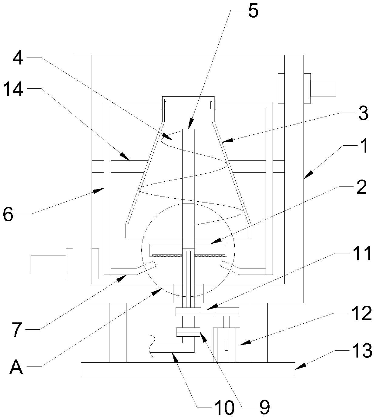
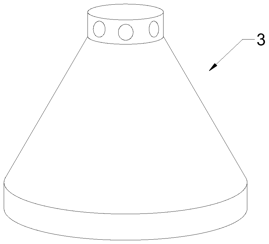
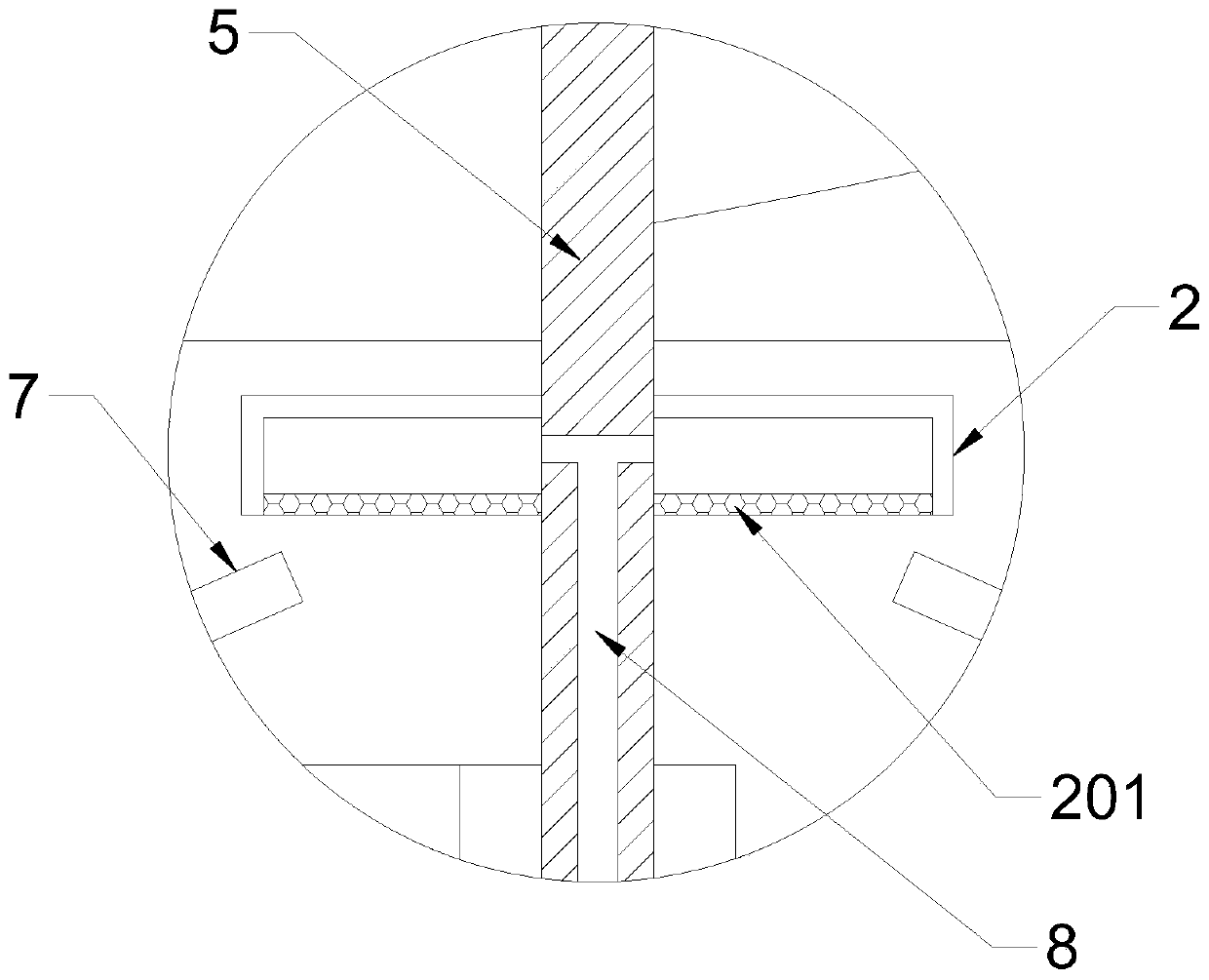
[0020] see Figure 1-3 , in the embodiment of the present invention, an environment-friendly and energy-saving aeration device comprises an aeration tank 1 and an aeration pan 2; Air hole 201; above the aeration disc 2 is provided with a guide tube 3, the guide tube 3 is a conical tube with an open lower end, inside the guide tube 3 is provided with a helical blade 4, and the helical blade 4 is fixedly connected with a central shaft 5 , the central axis 5 extends to the bottom of the aeration tank 1, the central axis 5 is connected to the output shaft of the drive motor 12 through the transmission belt 11, the drive motor 12 is fixedly connected to the base 13 by means of bolts, and the base 13 is fixed to the aeration tank 1 connected; the drive motor 12 drives the central shaft 5 and the spiral blade 4 to rotate through the transmission belt 11, and pushes the sewage at the bottom of the aeration tank 1 to the upper part of the inner cavity of the guide tube 3; the upper par...

Embodiment 2

[0023] The difference between this embodiment and Embodiment 1 is that: the lower end of the return pipe 6 is connected with a spray pipe 7, the diameter of the spray pipe 7 is smaller than the diameter of the return pipe 6, and the outlet end of the spray pipe 7 faces the aeration pan 2, and the spray pipe 7 is connected to the aeration pan. 2. The aeration holes on the lower end surface are flushed to improve the contact efficiency between the sewage and the air while avoiding the clogging of the aeration holes 201 to ensure the aeration effect.


PUM


Abstract

The invention discloses an environment-friendly energy-saving aeration device which comprises an aeration tank and an aeration disc. The aeration disc is arranged at the lower portion of the aerationtank. A flow guiding cylinder is arranged above the aeration disc, spiral blades are arranged inside the flow guiding cylinder, a center shaft is fixedly connected with the spiral blades, and circumferentially distributed return pipes are communicated with the upper portion of the flow guiding cylinder. By arranging the flow guiding cylinder, the spiral blades and the return pipes, vertical circulation of sewage is achieved, sewage repeatedly makes contact with gas sprayed by the aeration disc, the mixed dissolution efficiency is improved, the aeration time is shortened, and energy is saved; by arranging a spraying pipe with an opening towards the aeration disc, the aeration disc can be flushed, the common problem that an aeration hole is blocked is avoided, and the aeration efficiency isensured.

Description

technical field [0001] The invention relates to the field of aeration equipment, in particular to an environment-friendly and energy-saving aeration device. Background technique [0002] Aeration refers to the process of forcibly transferring the oxygen in the air to the liquid, the purpose of which is to obtain sufficient dissolved oxygen. In addition, aeration also has the purpose of preventing the suspension of the tank from sinking and strengthening the contact between the organic matter in the tank, microorganisms and dissolved oxygen. In this way, the microorganisms in the pool can oxidize and decompose the organic matter in the sewage under the condition of sufficient dissolved oxygen. [0003] The traditional aeration device is to set an aeration plate or multiple aeration tubes at the bottom of the aeration tank for aeration, and some aeration wheels are used to directly lift the sewage into contact with the air. The former air is injected into the sewage to form b...

Claims


Application Information

Patent Timeline
Patent Type & Authority Patents(China)
IPC IPC(8): C02F3/02
CPCC02F3/02Y02W10/10
Inventor 李静
Owner 李静
Why Eureka
Try Eureka