An energy-saving sewage treatment device

A sewage treatment device and water inlet pipe technology, applied in the direction of water/sewage multi-stage treatment, water/sludge/sewage treatment, flocculation/sedimentation water/sewage treatment, etc., can solve the problem of reducing the mixing effect, sedimentation efficiency, and static sedimentation efficiency Low, unfavorable large-scale treatment of sewage and other issues, to achieve the effect of improving the mixing effect and sedimentation efficiency, reducing power output

Active Publication Date: 2021-01-22
SOUTH CHINA UNIV OF TECH
View PDF7 Cites 0 Cited by
  • Summary
  • Abstract
  • Description
  • Claims
  • Application Information

AI Technical Summary

Problems solved by technology

[0002] Traditional sedimentation tanks for sewage treatment are purified by static sedimentation, which is inefficient and unfavorable for large-scale sewage treatment operations. In addition, traditional flocculants cannot be fully mixed with sewage through simple stirring devices after adding them, reducing the Mixing effect and sedimentation efficiency

Method used


Image

  • An energy-saving sewage treatment device
  • An energy-saving sewage treatment device
  • An energy-saving sewage treatment device

Examples


Embodiment 1

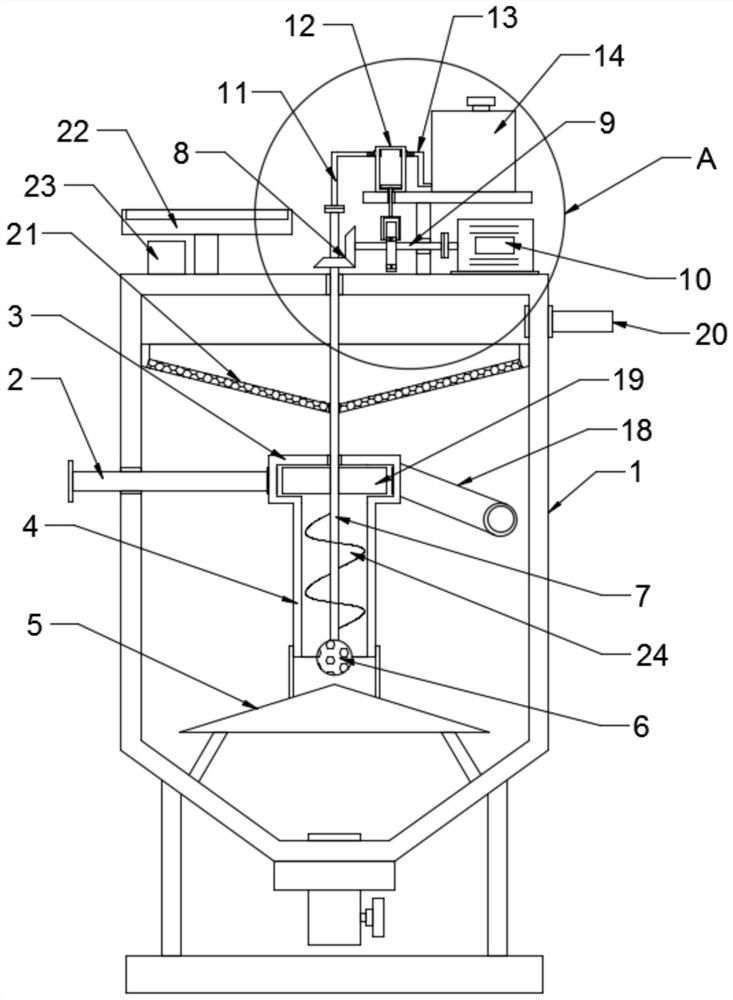
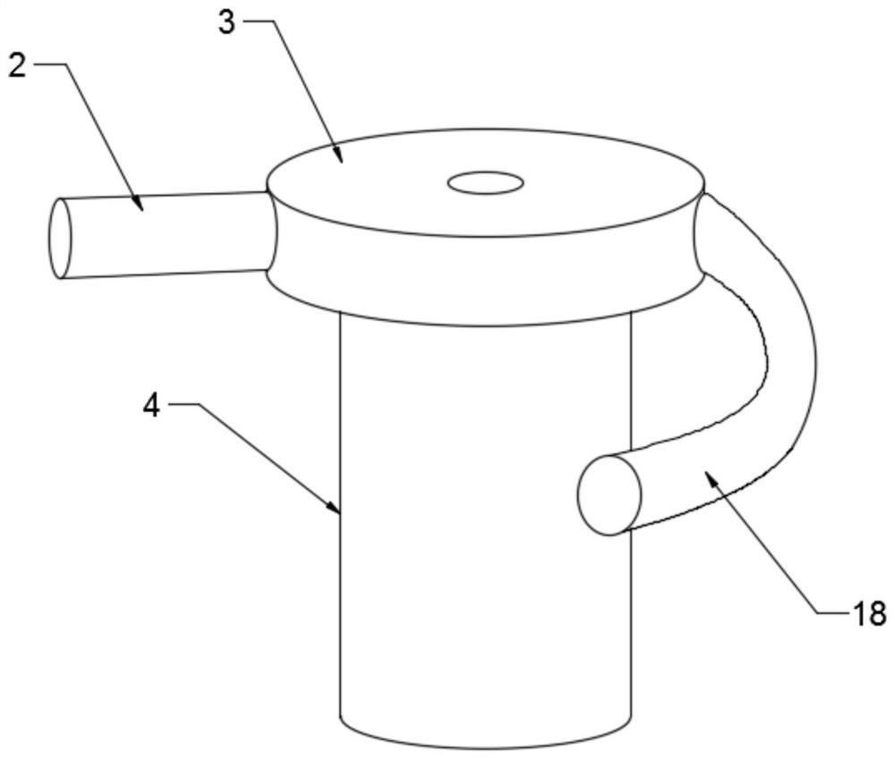
[0021] see Figure 1-5 In an embodiment of the present invention, an energy-saving sewage treatment device includes a tank body 1; a water inlet pipe 2 is provided on one side of the tank body 1, and the water inlet pipe 2 extends into the tank body, and the end of the water inlet pipe 2 is fixedly connected with a diffusion cylinder 3 , the water inlet pipe 2 is in tangential communication with the inner cavity of the diffusion cylinder 3, the sewage flows into the diffusion cylinder 3 tangentially, and the right side of the diffusion cylinder 3 is fixedly connected with a diversion elbow 18, and the diversion elbow 18 extends to the inner wall of the tank body 1; The diffusion cylinder 3 is nested with impeller plates 19 distributed in a circle, and the outer end of the impeller plate 19 abuts and slides against the inner wall of the diffusion cylinder 3; the impeller plate 19 is fixedly connected with the hollow shaft 7, specifically, the sewage enters the In the diffusion ...

Embodiment 2

[0026] The difference between this embodiment and Embodiment 1 is that in order to improve the sewage precipitation effect, the upper part of the tank body 1 is provided with an outlet pipe 20, and the inner wall of the tank body 1 is fixedly connected with a conical filter screen 21. The bottom and the surface are evenly opened with a conical net cover with mesh holes to filter the sewage discharged from the overflow. At the same time, under the action of the sewage swirl, the water flow continuously scours the lower end surface of the conical filter screen 21 to avoid clogging of the filter mesh and improve the filtration efficiency. Efficiency, to ensure the filtering effect.

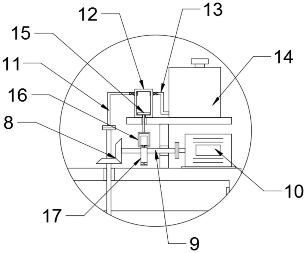
[0027] In order to simplify the driving mechanism, the liquid supply mechanism includes a pumping piston cylinder 12 and a liquid medicine tank 14, the liquid suction piston cylinder 12 communicates with the liquid medicine tank 14 through a liquid suction pipe 13, and the liquid flocculant is filled ...


PUM


Abstract

The invention discloses an energy-saving sewage treatment device, which comprises a tank body; a water inlet pipe is arranged on one side of the tank body, and a diffusion cylinder is fixedly connected to the end of the water inlet pipe; A diversion elbow is fixedly connected; the lower end of the diffusion cylinder is connected with a lifting cylinder integrally formed with it, and a spray ball is arranged under the lifting cylinder. By setting the water inlet pipe and diversion elbow respectively connected tangentially with the diffusion cylinder, the sewage forms a swirling flow in the tank, accelerates the accumulation and settlement of sedimentation, and at the same time drives the hollow shaft to rotate, reduces the power output of the motor, and achieves energy-saving effects; Through the installation of lifting cylinder, impeller plate, helical lifting blade, spray ball and hollow shaft, the sewage can be circulated up and down while the flocculant and sewage are fully mixed and lifted for swirl settlement, which improves the mixing effect and sedimentation efficiency.

Description

technical field [0001] The invention relates to the field of environmental protection equipment, in particular to an energy-saving sewage treatment device. Background technique [0002] Traditional sedimentation tanks for sewage treatment are purified by static sedimentation, which is inefficient and unfavorable for large-scale sewage treatment operations. In addition, traditional flocculants cannot be fully mixed with sewage through simple stirring devices after adding them, reducing the The mixing effect and sedimentation efficiency were improved. Contents of the invention [0003] The purpose of the present invention is to provide an energy-saving sewage treatment device to solve the problems raised in the above-mentioned background technology. [0004] To achieve the above object, the present invention provides the following technical solutions: [0005] An energy-saving sewage treatment device, comprising a tank body; one side of the tank body is provided with a wat...

Claims


Application Information

Patent Timeline
Patent Type & Authority Patents(China)
IPC IPC(8): C02F9/04B01F5/00B01F5/10B01F15/00B01F15/02
CPCC02F1/001C02F1/52B01F25/00B01F2025/9121B01F2025/93B01F25/52B01F35/31B01F35/3204B01F35/187B01F35/7179B01F2101/305
Inventor 牛立山
Owner SOUTH CHINA UNIV OF TECH
Why Eureka
Try Eureka