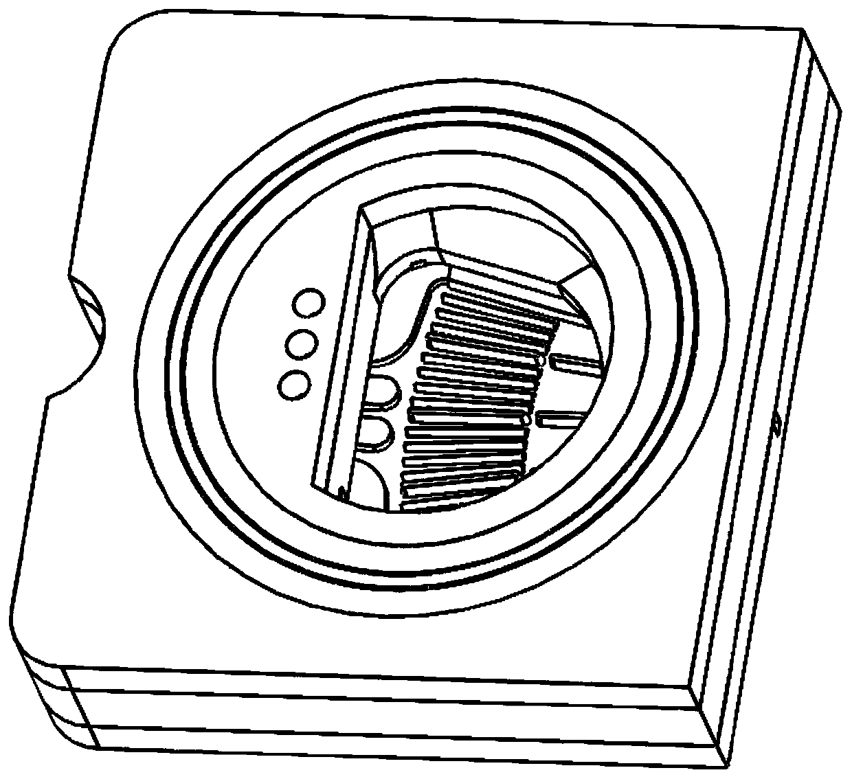
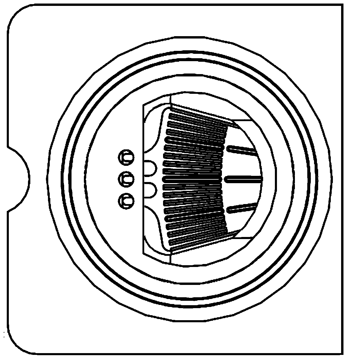
Sample introduction chamber for micro-fluidic chip, and single index micro-fluidic chip

A technology of a microfluidic chip and a sample injection chamber, which is applied in the field of sample injection chambers, can solve the problems that the quantification of the reaction chamber cannot be well achieved, the serum filtration pressure is large, and the sample is easily retained, so as to facilitate detection and increase the reaction volume. , the effect of improving filtration efficiency

Pending Publication Date: 2019-08-16
NANJING LANSION BIOTECH CO LTD
View PDF4 Cites 7 Cited by
  • Summary
  • Abstract
  • Description
  • Claims
  • Application Information

AI Technical Summary

Problems solved by technology

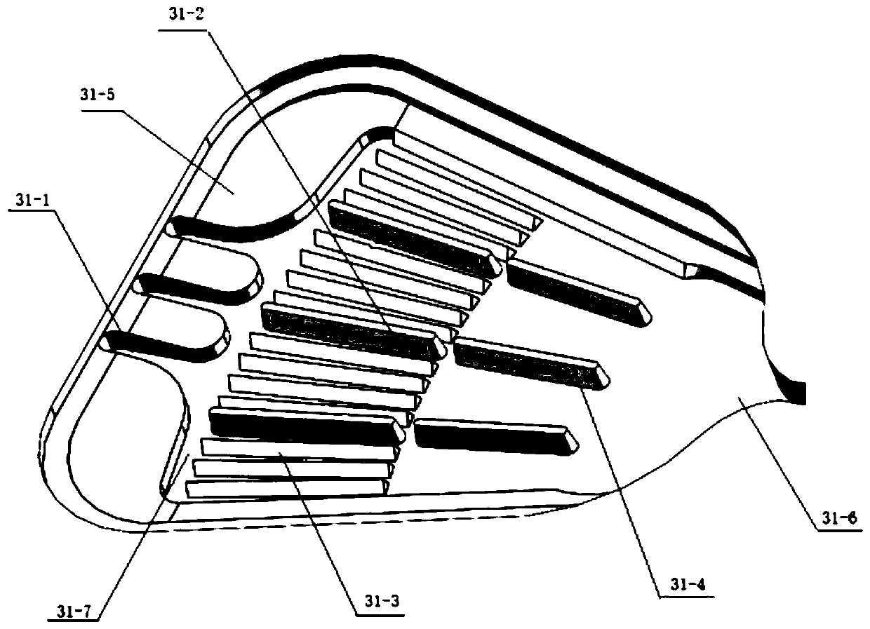
[0006] Through practical application, the applicant found that although the filter pool mentioned in Chinese patent 201910018240.7 is equipped with flow guide strips, the number, shape and size of the flow guide strips at the wide end and narrow end of the filter sample pool are the same. Therefore, the sample It is easy to stay at the front end of the diversion bar and the sample pool, wasting samples
In addition, the arrangement of the diversion strips results in a high pressure for the serum to be filtered out, which can easily cause the serum to be absorbed into the blood filter paper.
[0007] In addition, in the applicant's previous research, including the above-mentioned published Chinese patent, the microfluidic channels entering and exiting the reaction chamber are all set on the front of the lower chip. Therefore, in actual use, the gas tends to occupy the upper part of the reaction chamber, resulting in insufficient serum. The reaction chamber is flowing out, that is, the quantification of the reaction chamber cannot be well realized

Method used


Image

  • Sample introduction chamber for micro-fluidic chip, and single index micro-fluidic chip
  • Sample introduction chamber for micro-fluidic chip, and single index micro-fluidic chip
  • Sample introduction chamber for micro-fluidic chip, and single index micro-fluidic chip

Examples


Embodiment Construction

[0062] The following will clearly and completely describe the technical solutions in the embodiments of the present invention with reference to the accompanying drawings in the embodiments of the present invention. Obviously, the described embodiments are only some, not all, embodiments of the present invention. The following description of at least one exemplary embodiment is merely illustrative in nature and in no way taken as limiting the invention, its application or uses. Based on the embodiments of the present invention, all other embodiments obtained by persons of ordinary skill in the art without creative efforts fall within the protection scope of the present invention. The relative arrangements, expressions and numerical values ​​of components and steps set forth in these embodiments do not limit the scope of the present invention unless specifically stated otherwise. At the same time, it should be understood that, for the convenience of description, the sizes of the...


PUM


Abstract

The invention discloses a sample introduction chamber for a micro-fluidic chip, and a single index micro-fluidic chip. The sample introduction chamber for the micro-fluidic chip comprises a sample filtering cell and a sample introduction portion arranged at the cell mouth of the sample filtering cell; the sample filtering cell is arranged in a palm-leaf fan shape, the liquid outlet of the sample filtering cell is arranged in the narrow sidewall, and the bottom of the sample filtering cell is provided with flow guiding zones; the sample introduction portion is provided with air holes, air guiding grooves are arranged in the positions, close to the wide sidewall of the bottom of the sample filtering cell and correspond to the air holes, and an air gathering zone is arranged between all the air guiding grooves and the flow guiding zones; and every air guiding groove is communicated with the corresponding air hole, and every air guiding groove is communicated with the flow guiding zones through the air gathering zone. The bottom of the sample filtering cell is provided with the air guiding grooves, and the air gathering zone is arranged between the air guiding grooves and the flow guiding zones, so air can be easily discharged during sample introduction, and bubbles are reduced.

Description

technical field [0001] The invention relates to a sample injection cavity of a microfluidic chip. [0002] The present invention also relates to a single-index microfluidic chip comprising the above-mentioned sample injection chamber. Background technique [0003] Immunolateral flow-through diagnostic technology is a stable and practical technology suitable for use in various point-of-care tests (POCT) or on-site. In the immunochromatographic reaction system, due to system reasons, the CV is large and accurate quantification cannot be achieved. The immunodiagnostic method based on microfluidic technology can effectively avoid the above problems. [0004] There are two types of microfluidics: passive and active. Among them: Passive microfluidics requires capillary force to achieve liquid-forward lateral flow. However, due to the different viscosities of different samples, especially whole blood samples, the liquid flow rate cannot be uniform. Active microfluidics can eff...

Claims


Application Information

Patent Timeline
Patent Type & Authority Applications(China)
IPC IPC(8): B01L3/00
CPCB01L3/5027
Inventor 许行尚杰弗瑞·陈于沛孙威严
Owner NANJING LANSION BIOTECH CO LTD
Why Eureka
Try Eureka