
Mold with movable mold cavities

A technology of movable cavity and mould, which is applied in the field of moulds, can solve the problems of uneven thickness, difficult molding, large internal stress, etc., and achieve the effects of not easy to separate from each other, easy to flow, and good internal stress

Pending Publication Date: 2019-08-16
KAIPING YINGGUANG ELECTROMECHANICAL TECH
View PDF0 Cites 2 Cited by
  • Summary
  • Abstract
  • Description
  • Claims
  • Application Information

AI Technical Summary

Problems solved by technology

[0004] At present, the molds for product molding in the mold industry all use glue injection into the fixed cavity. The volume of the fixed cavity is the same as the volume of the product. During the molding process, the fixed cavity is too small to cause the flow of raw materials. The resistance is large, and it is not easy to form. In order to achieve product forming, the injection pressure and injection speed must be increased, which leads to large internal stress of the formed product, poor appearance, uneven thickness, and easy separation of composite materials, resulting in poor product quality. , low yield

Method used


Image

  • Mold with movable mold cavities
  • Mold with movable mold cavities
  • Mold with movable mold cavities

Examples


Embodiment Construction

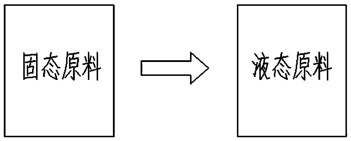
[0031] The mold with movable cavity of the present invention is suitable for producing thin-walled products, battery back covers, mobile phone shells or optical products, and the materials used are high-viscosity materials or low-viscosity materials, composite materials that are not easy to separate from each other or easy to separate from each other composite material.

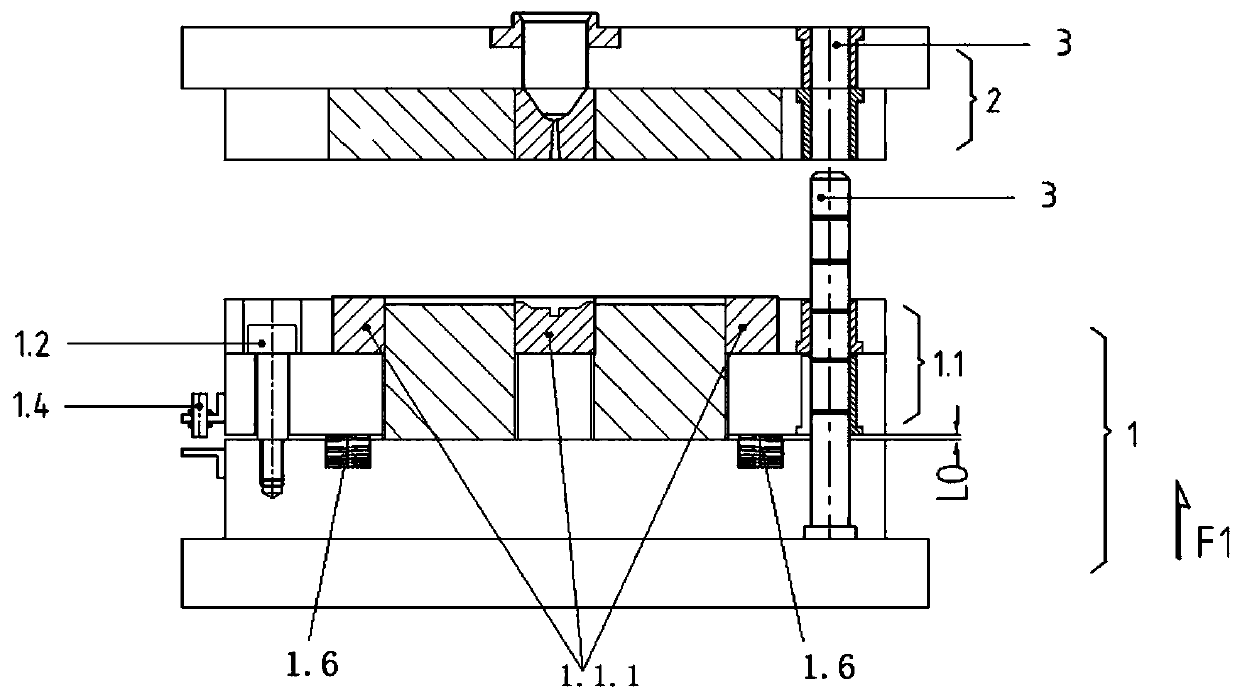
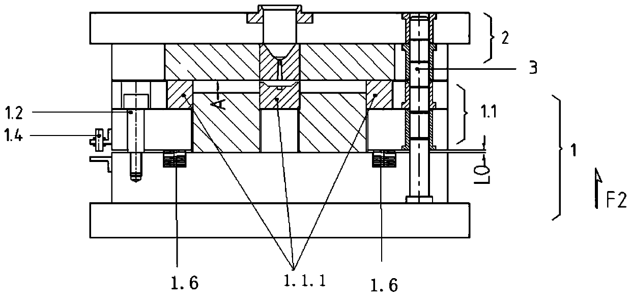
[0032] refer to figure 1 , figure 2 , image 3 , Figure 4 , Figure 5 , Image 6 , Figure 7 , Figure 8 , Figure 9 , Figure 10 , Figure 11 , Figure 12 , Figure 13 , Figure 14 , Figure 15 , Figure 16 and Figure 17 , the preferred embodiment and other embodiments of the mold with movable cavity of the present invention are described in detail.

[0033] The invention provides a mold with a movable cavity, which includes a movable mold 1 and a fixed mold 2, the movable mold 1 is provided with a movable mold support device 1.10, and the fixed mold 2 is provided with a fixed mold support...


PUM

PropertyMeasurementUnit
thicknessaaaaaaaaaa

Abstract

The invention provides a mold with movable mold cavities. The mold comprises a movable mold body and a fixed mold body, the movable mold body is provided with a movable mold body supporting device, the fixed mold body is provided with a fixed mold body supporting device, the movable mold body and the fixed mold body cooperate with each other, the movable mold body is provided with movable mold body mold cores, and the fixed mold body is provided with fixed mold body mold cores. The mold is characterized in that the mold further comprises guiding assemblies, water channel devices and positioning structures, the movable mold body comprises a second-time moving mechanism and a limiting device, and the second-time moving mechanism is movably connected with the movable mold body through the guiding assemblies and the limiting device. According to the mold with movable mold cavities, the movable mold cavities are arranged, the volume of the movable mold cavities can be adjusted according tothe requirements of products, the volume of the movable mold cavities before compression stopping is larger than the size of the products, liquid-state raw materials can easily flow in the movable mold cavities with the large volume, the products are easy to form at low speed or under low pressure, and the products have the advantages that the internal stress is good, the appearance is beautiful,the thickness is uniform, and composite materials are not prone to being separated from one another.

Description

technical field [0001] The invention relates to a mold, in particular to a mold with a movable cavity. Background technique [0002] Injection mold is a tool for producing plastic products, and it is also a tool for giving plastic products complete structure and precise dimensions. Injection molding is a processing method used in the mass production of certain complex-shaped parts. Specifically, it refers to injecting the heated and melted plastic into the mold cavity under high pressure from the injection molding machine, and after cooling and solidifying, a molded product is obtained. [0003] The injection mold consists of two parts, the movable mold and the fixed mold. The movable mold is installed on the movable template of the injection molding machine, and the fixed mold is installed on the fixed template of the injection molding machine. Both the movable mold and the fixed mold form a fixed cavity. Size cannot be changed. During injection molding, the movable mold...

Claims


Application Information

Patent Timeline
Patent Type & Authority Applications(China)
IPC IPC(8): B29C45/26B29C45/34B29C45/36
CPCB29C45/26B29C45/2602B29C45/34B29C45/36B29C2045/2697B29C2045/363
Inventor 徐雄石茂东陈林
Owner KAIPING YINGGUANG ELECTROMECHANICAL TECH
Learn More