A spring energy storage jumping mechanism

An energy storage, spring shaft technology, applied in the field of robotics, can solve problems such as overall structure rotation, increasing overall structure and control program complexity, and non-uniform spring compression speed.

An energy storage, spring shaft technology, applied in the field of robotics, can solve problems such as overall structure rotation, increasing overall structure and control program complexity, and non-uniform spring compression speed.

CN110126933BActive Publication Date: 2021-12-14NANJING UNIV OF AERONAUTICS & ASTRONAUTICS

Image

  • A spring energy storage jumping mechanism
  • A spring energy storage jumping mechanism
  • A spring energy storage jumping mechanism

Examples


Embodiment Construction

[0025] The invention will be further described below with reference to the accompanying drawings.

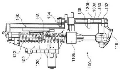
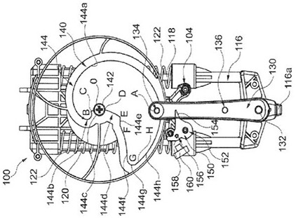
[0026] figure 1 and 2 Shows a jump mechanism described in US 20150352454 A1, the entire structure represented by reference numeral 100.

[0027] The structure 116 comprises a sliding portion, the sliding portion 116 is rigidly secured to the rods 118 and slidably received in the base 102 integrally with the two cylinders 120. For two energy storage spring 122 and 118 respectively around the two rods placed in their respective cylinders 120, one end 116b is supported on a shoulder formed at the sliding portion 116 coaxially with rod 118, the rod 118 of the root . Upper shoulder 104 formed on the cylinder 120, the opposite of the hole opposite thereto, an end portion 118 joined by respective rod.

[0028] When the sliding portion 116 moves closer to the base of the carriage 102 when the compression spring accumulator, when the sliding portion 116 slides backward, the spring pushing t...


PUM


Abstract

The invention belongs to the technical field of robots, and discloses a spring energy storage type jumping mechanism, comprising: a track turntable (1), a pull rod (4), a spring energy storage device (15), the front end of the pull rod (4) and the track turntable The track of (1) is connected and can move on the track, the rear end of the pull rod (4) is connected with the spring energy storage device (15), the track of the track turntable (1) is Archimedes spiral, the The track turntable (1) is a worm gear structure, and the jumping mechanism also includes a worm, which meshes with the worm wheel, and drives the worm wheel to rotate by rotating the worm. The driving torque realizes the compression of a spring with greater elastic force, so that the jumping height of the jumping mechanism is higher, and the jumping mechanism can be widely used in small jumping robots.

Description

Technical field [0001] The present invention belongs to the field of robotics, in particular to a spring energy storage mechanism jump. Background technique [0002] A variety of robot jumping mechanism classification, according to the driving mode can be divided into hydraulic drives, pneumatic drives and motors driving mode such as a spring, but the complexity of the hydraulic drive and pneumatic drive structure, and large volume mass, problems such as complicated control, are not suitable for Research on small hopping robot, and general motor-driven spring-like hopping mechanism is unreasonable because it is designed, resulting in less storage, jump height is low, problems such as a larger volume. So the type of robot jumping agencies such as are described in US20150352454 A1. It is generally disc-shaped rotary member, the sliding portion, a spring and a driving motor. [0003] This structure has the following disadvantages: [0004] (1) a substantially disc-shaped cam surface...

Claims


Application Information

Patent Timeline
14 Dec 2021
Publication
CN110126933B
IPC
B62D57/02
CPC
B62D57/02
Inventors
张子建; 曹童波