Composite support bridge plane rotating system

A swivel and bridge technology, which is applied in the field of plane swivel system of combined bearing bridges, can solve the problems of unfavorable force bearing, uneconomical pile foundation design, and low anti-overturning ability, so as to achieve stable and reliable supporting structure and improve anti-overturning stability , Improve the effect of anti-overturning ability

Pending Publication Date: 2019-08-16
CREEC WUHAN SURVEY DESIGN & RES
View PDF0 Cites 11 Cited by
  • Summary
  • Abstract
  • Description
  • Claims
  • Application Information

AI Technical Summary

Problems solved by technology

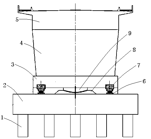
[0004] (1) The single-spherical hinge rotation method is a single-point support system, and only the central spherical hinge transmits load between the upper and lower turntables. When the bridge is wider, the force on the upper and lower turntables is unfavorable, and the caps need to be increased thick and equipped with a large number of prestressed tendons; and because the load is concentrated near the center spherical joint, only a part of the pile foundation near the center of the pile foundation at the lower part of the cap bears the vertical load during the rotation stage, and the force is extremely uneven, and the pile length is affected by the vertical load. Controlled by several piles with high force in the middle, the pile foundation design is not economical
[0005] (2) For high-rise structures such as continuous girders with high piers and cable-stayed bridges, they are greatly affected by wind loads, and the risk of bridge tilting during rotation is relatively high. The friction force of the lower spherical surface resists the overturning moment generated by the horizontal wind load, and the overall anti-overturning ability is low. Other auxiliary measures need to be taken to improve the anti-overturning stability during rotation

Method used


Image

  • Composite support bridge plane rotating system
  • Composite support bridge plane rotating system
  • Composite support bridge plane rotating system

Examples


Embodiment Construction

[0028] The following will clearly and completely describe the technical solutions in the embodiments of the present invention with reference to the accompanying drawings in the embodiments of the present invention. Obviously, the described embodiments are only some, not all, embodiments of the present invention. Based on the embodiments of the present invention, all other embodiments obtained by persons of ordinary skill in the art without making creative efforts belong to the protection scope of the present invention.

[0029] In describing the present invention, it is to be understood that the terms "center", "upper", "lower", "front", "rear", "left", "right", "vertical", "horizontal", The orientations or positional relationships indicated by "top", "bottom", "inner", "outer", etc. are based on the orientations or positional relationships shown in the drawings, and are only for the convenience of describing the present invention and simplifying the description, rather than in...


PUM


Abstract

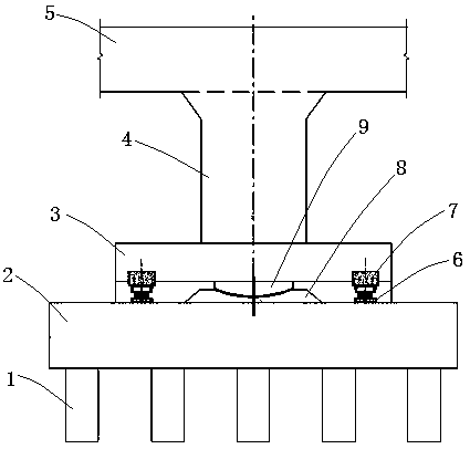
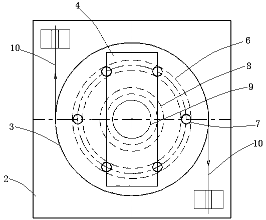
The invention provides a composite support bridge plane rotating system. The composite support bridge plane rotating system comprises a lower bearing platform structure, a center spherical hinge, a rotary table for supporting a to-be-rotated bridge, and a power mechanism for driving the rotary table to rotate, a supporting platform for supporting the center spherical hinge is arranged on the lowerbearing platform structure, the center spherical hinge is rotatably installed at the bottom of the rotary table, and arranged corresponding to the central area at the bottom of a pier of the to-be-rotated bridge, a ring-shaped track is arranged on the position, on the outer side of the supporting platform, of the lower bearing platform structure, and a plurality of idler wheel trolleys for supporting the rotary table are arranged on the ring-shaped track in a travelling mode. According to the composite support bridge plane rotating system, the center spherical hinge and the idler wheel trolleys are used for being subjected to force bearing jointly, multi-point support is formed on the to-be-rotated bridge, the problem that the loads of existing single-spherical-hinge rotating bodies are all centralized near the center spherical hinge to be transferred, and consequently the lower bearing platform structure is unevenly stressed is solved, and the anti-overturning stability in the rotating process is greatly improved.

Description

technical field [0001] The invention belongs to the technical field of bridge design and construction, and in particular relates to a planar swivel system of a combined support bridge. Background technique [0002] Compared with construction methods such as bracket cast-in-place, hanging basket suspension and prefabricated erection, bridge swivel construction has the shortest impact on the traffic operation of existing railways and highways. And highway and other projects have been widely used. [0003] At present, the plane swivel of the bridge adopts the single spherical hinge swivel system, but this method has some limitations: [0004] (1) The single-spherical hinge rotation method is a single-point support system, and only the central spherical hinge transmits load between the upper and lower turntables. When the bridge is wider, the force on the upper and lower turntables is unfavorable, and the caps need to be increased thick and equipped with a large number of pres...

Claims


Application Information

Patent Timeline
Patent Type & Authority Applications(China)
IPC IPC(8): E01D21/08
CPCE01D21/08
Inventor 李前名邹向农吴中文马行川龙俊贤张峰李文江宋伟
Owner CREEC WUHAN SURVEY DESIGN & RES
Why Eureka
Try Eureka