Valve stem coupled high-pressure common rail injector

A high-pressure common rail and fuel injector technology, applied in engine components, machines/engines, fuel injection devices, etc., can solve the problems of scrapped fuel injectors, drop of fuel injection pressure, poor sealing performance of fuel injectors, etc. The effect of reducing the use and maintenance costs

Pending Publication Date: 2019-08-16
无锡格林鲍尔科技有限公司
View PDF0 Cites 2 Cited by
  • Summary
  • Abstract
  • Description
  • Claims
  • Application Information

AI Technical Summary

Problems solved by technology

[0005] In this high-pressure common rail injector, the valve stem 2 and the valve body 1 have a precision clearance fit structure. The device will be completely scrapped
At the same time, since there is high-pressure oil between the top of the valve stem 2 and the valve stem fitting hole 14, the valve stem fitting hole 14 of the valve body 1 will expand and deform the diameter of the valve stem fitting hole 14 under high pressure during work, so that The fit gap between the valve stem 2 and the valve stem fitting hole 14 increases, the sealing performance of the entire injector is not good, and the defect of fuel injection pressure drop is prone to occur

Method used


Image

  • Valve stem coupled high-pressure common rail injector
  • Valve stem coupled high-pressure common rail injector
  • Valve stem coupled high-pressure common rail injector

Examples


specific Embodiment approach

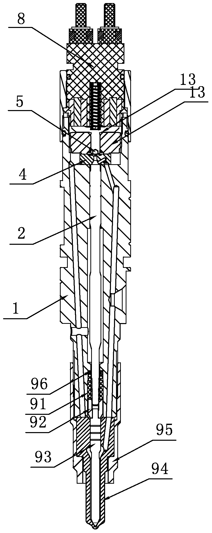
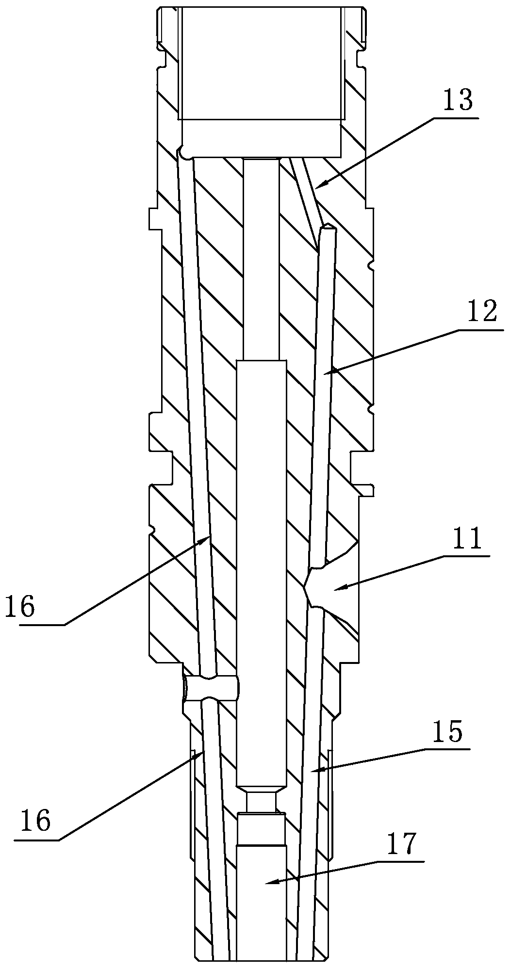
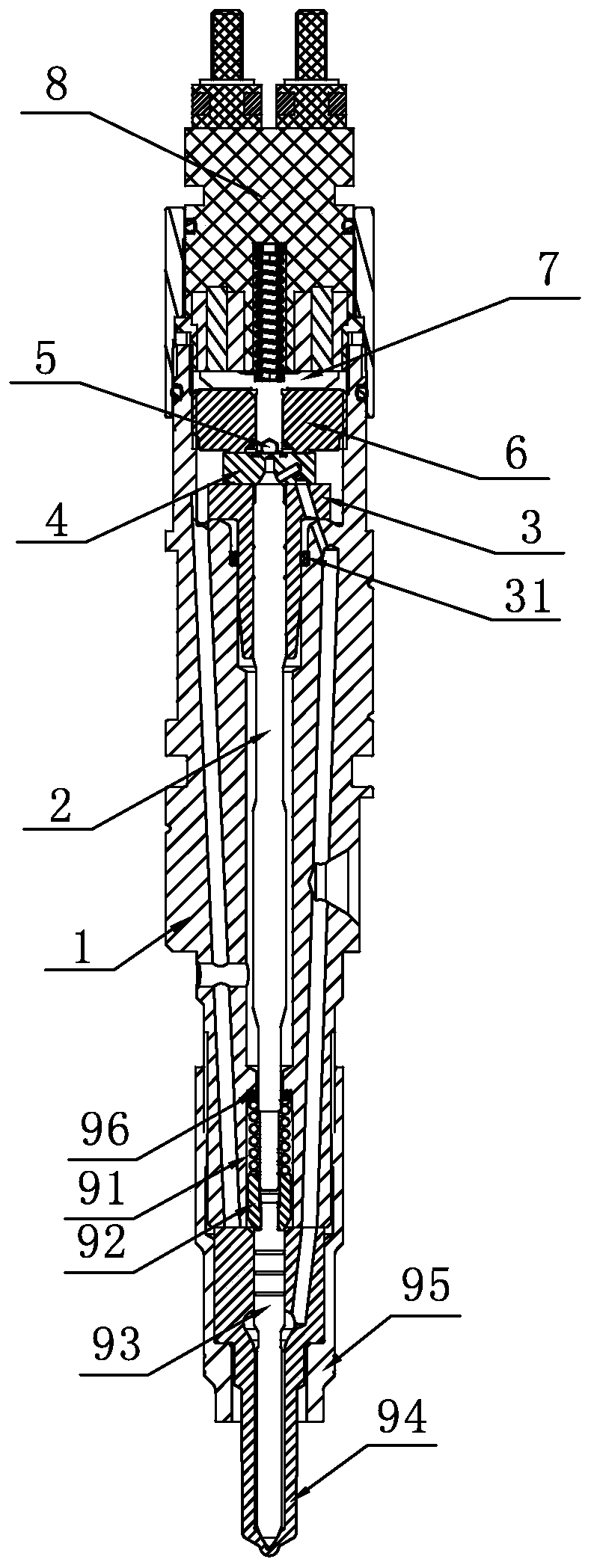
[0022] A high-pressure common rail fuel injector with valve stem coupling, Figure 3-Figure 5 As shown, it includes valve body 1, valve stem 2, valve stem sleeve 3, throttle body 4, sealing ball 5, iron-absorbing seat 6, iron-absorbing rod 7, solenoid valve parts 8, needle compression spring 91, double guide sleeve 92, The fuel injection valve needle 93, the fuel injection coupler sleeve 94 and the locking cap 95 are provided with an oil inlet hole 11, an upper and outer oil inlet passage 12, an oblique oil outlet hole 13, a lower outer oil inlet passage 15, Pressure relief oil passage 16, lower guide hole 17, pressure balance hole 18, valve stem sleeve seat hole 19, the valve stem sleeve 3 includes a shaft shoulder seat 31, a matching sleeve 32 and an oil inlet hole 33, and the valve stem sleeve 3 is matched by The sleeve 32 is installed in the valve stem sleeve seat hole 19, and there is a clearance fit between the two. The shoulder seat 31 is in contact with the upper end s...


PUM


Abstract

A valve stem coupled high-pressure common rail injector comprises a valve body, a valve stem and a valve stem sleeve. A pressure balance hole and a valve stem sleeve seat hole are arranged on the valve body, and the valve stem sleeve is installed in the valve stem sleeve seat hole through a matching sleeve. A shaft shoulder seat is in contact with the upper end surface of the pressure balance hole, and the diameter of the pressure balance hole is larger than the outer diameter of the matching sleeve. The lower end of an oil inlet hole communicates with the pressure balance hole. The inner holeand the valve stem sleeve is in coupled precise clearance fit with the valve rod, and a seal ring is arranged between the pressure balance hole and the outer diameter of the valve stem sleeve. According to the valve stem coupled high-pressure common rail injector, the valve stem and the valve stem sleeve are coupled, and a replaceable matched structure is adopted between the valve stem sleeve andthe valve body; in this way, when the fit clearance between the valve stem and the valve stem sleeve is out of tolerance due to wear, the valve stem sleeve and the valve stem can be directly replaced, and the use and maintenance cost of the injector can be greatly lowered. The arranged pressure balance hole can eliminate the situation that pressure deformation of the inner hole of the valve stemsleeve causes the fit clearance between the valve stem and the matching hole to be enlarged; and the seal ring is arranged between the pressure balance hole and the outer diameter of the valve stem sleeve to prevent leakage.

Description

[0001] Technical field: [0002] The patent of the present invention relates to an electronically controlled common rail fuel injector for diesel engines. [0003] Background technique: [0004] The structure of the prior art fuel injector assembly is as follows: figure 1 , figure 2 As shown, it includes valve body 1, valve stem 2, valve stem sleeve 3, throttle body 4, sealing ball 5, iron absorbing seat 6, iron absorbing rod 7, solenoid valve part 8, valve needle compression spring 91, double guide sleeve 92 , the fuel injection valve needle 93, the fuel injection coupler set 94 and the locking cap 95, the valve body 1 is provided with an oil inlet hole 11, an upper and outer oil inlet passage 12, an oblique oil outlet hole 13, a valve stem matching hole 14, The lower outer oil inlet passage 15, the pressure relief oil passage 16 and the lower guide hole 17, and the valve stem 2 are installed in the valve stem matching hole 14 of the valve body 1 in a clearance fit manner. ...

Claims


Application Information

Patent Timeline
IPC IPC(8): F02M51/06F02M47/02F02M61/12F02M61/16
CPCF02M51/061F02M47/027F02M61/12F02M61/16
Inventor 刘义亭吴小勇庄福如沙有胜鞠得雨王进钱音瑶赵波李明
Owner 无锡格林鲍尔科技有限公司
Why Eureka
Try Eureka