Drum type flying shears and gear pair return-clearance adjustment method

A flying shear and drum-type technology, which is applied to belts/chains/gears, shearing devices, mechanical equipment, etc., can solve problems such as difficult adjustments and poor shearing quality, and achieve simple equipment, high work efficiency, and reduced The effect of equipment weight

Active Publication Date: 2009-06-10
CHINA FIRST HEAVY IND +1
View PDF0 Cites 9 Cited by
  • Summary
  • Abstract
  • Description
  • Claims
  • Application Information

AI Technical Summary

Problems solved by technology

[0004] The purpose of the present invention is to provide a kind of drum type flying shears in order to overcome the shortcoming and deficiency of existing drum type flying shears. It overcomes the shortcoming of the poor cutting quality of the existing flying shears, enables the cut head and tail parts to be reliably separated from the strip blank, and realizes the continuous breaking and shearing function; at the same time, the two pairs of synchronous gear pairs and the The connection method is changed from the key connection to the full hydraulic pressure-fitted keyless connection, so that the matching synchronous gear pair on the transmission side is engaged for transmission when the flying shear is started, and the paired synchronous gear pair on the operating side is engaged for transmission when the flying shear is braking. The existing main and auxiliary gear structure and shear blade adjustment device with complex structure and difficult adjustment are eliminated, making the equipment structure simpler

Method used


Image

  • Drum type flying shears and gear pair return-clearance adjustment method
  • Drum type flying shears and gear pair return-clearance adjustment method
  • Drum type flying shears and gear pair return-clearance adjustment method

Examples


Embodiment Construction

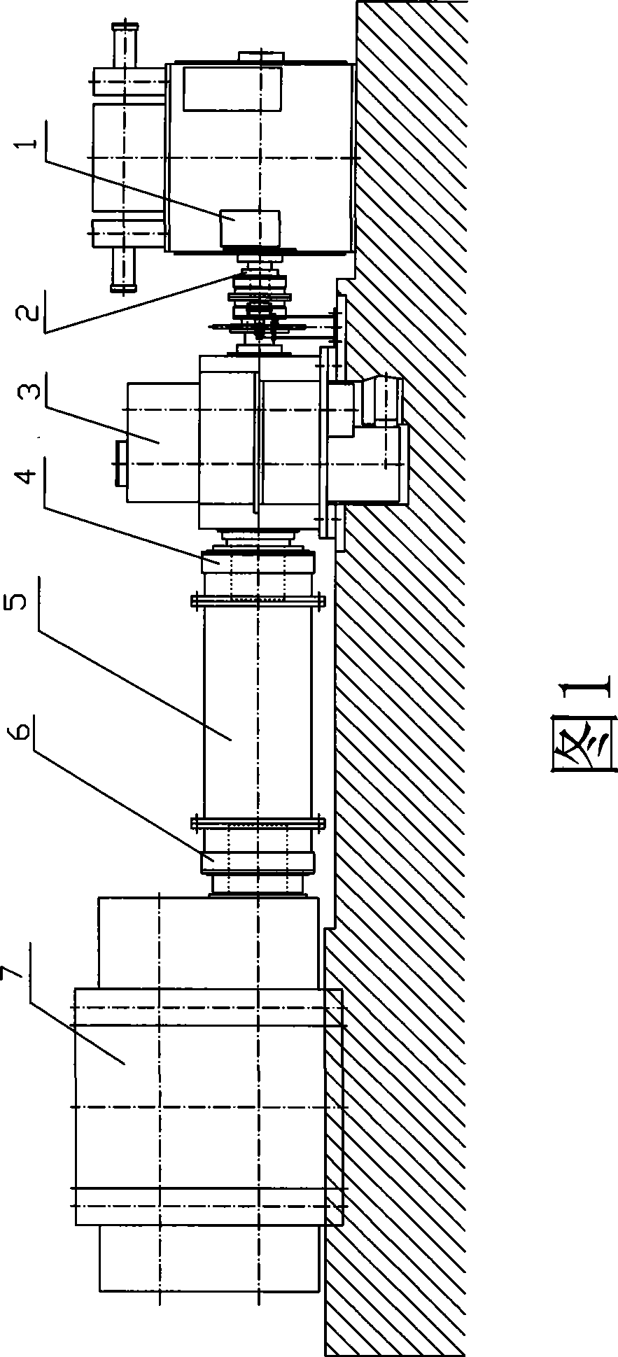
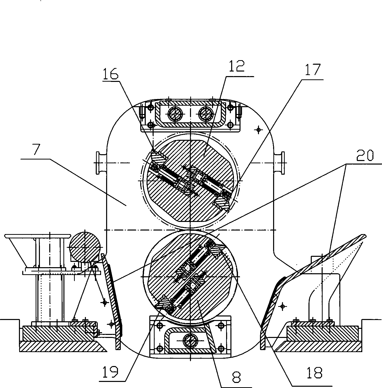
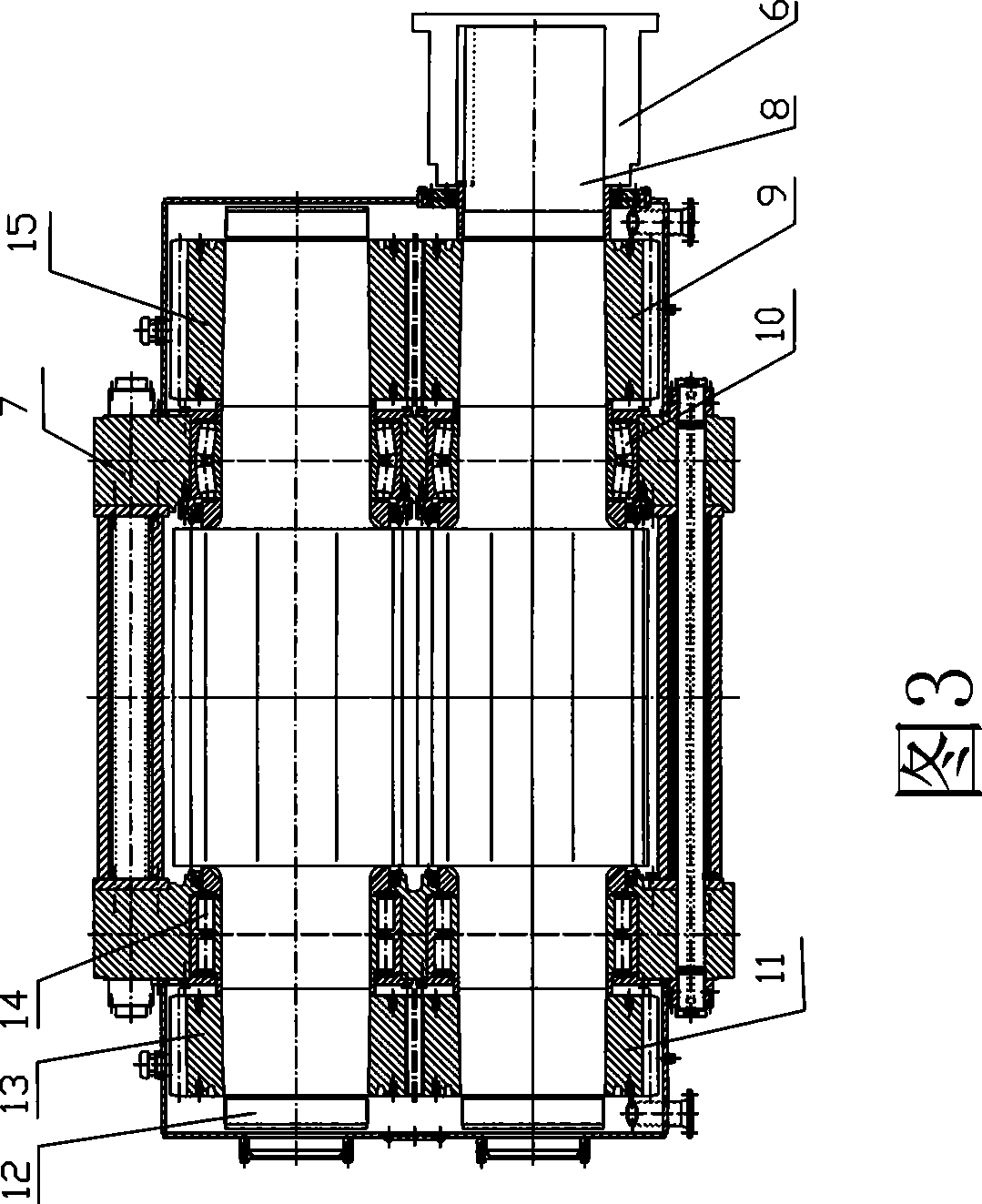
[0024] A drum-type flying shear machine as shown in Figures 1 to 3, including a motor 1, a coupling with a brake disc 2, a reducer 3, a coupling I 4, a transmission shaft 5, and a coupling II 6 , flying shear body 7, lower drum 8, gear I9, bearing I10, gear II 11, upper drum 12, gear III 13, bearing II 14, gear IV 15, cutting head upper cutting edge 16, cutting tail upper cutting edge 17 , cutting tail lower cutting edge 18, cutting head lower cutting edge 19 and baffle plate 20; the output shaft of motor 1 is fixedly connected with the input shaft of reducer 3 through coupling 2 with brake disc, and the output shaft of reducer 3 is through the coupling I 4 is fixedly connected with the transmission shaft 5, and the transmission shaft 5 is fixedly connected with the lower drum 8 through the coupling II 6; the lower drum 8 and the upper drum 12 are respectively supported on the flying shear body 7 by the bearing I 10 and the bearing II 14 The two ends of upper and lower drums 8...


PUM


Abstract

The invention discloses a rotary-drum type fly-shearing machine and a method for adjusting gear-pair return clearance. The rotary-drum type fly-shearing machine is shearing equipment used for shearing the head, tail, low-temperature and irregular parts of strip stock after rough rolling. The fly-shearing machine comprises a motor, a speed reducer, a transmission shaft, a fly-shearing machine body, a lower rotary drum, an upper rotary drum, a head-cutting upper shearing blade, a tail-cutting upper shearing blade, a tail-cutting lower shearing blade and a head-cutting lower shearing blade, wherein the motor is connected with the lower rotary drum through the speed reducer and the transmission shaft; a gear I, a gear II, a gear III and a gear IV are pressed and arranged on cone shafts at two ends of the upper rotary drum and the lower rotary drum through hydraulic oil respectively; and the upper rotary drum and the lower rotary drum are symmetrically provided with a pair of shearing blades respectively. A transmission side is in mesh transmission with a synchronous gear pair when the fly-shearing machine is in a started state, and an operation side is in mesh transmission with the synchronous gear pair when the fly-shearing machine is in a braked state, so that the prior master-minor gear structure and shearing-blade adjustment device which are complex in structure and difficult to adjust are cancelled, and the structure is simple. In addition, the gear-pair return clearance can be adjusted and eliminated through the repeated assembly of gear pairs and the rotary drums, so as to improve the utilization rate of equipment.

Description

technical field [0001] The invention relates to a drum-type flying shear, which is used for shearing the low-temperature and irregular parts of the head and tail of a strip after rough rolling. Background technique [0002] Due to its good rotation balance and high shearing speed, the rotary drum flying shear can be equipped with two pairs of shearing blades for cutting the head and tail respectively, can quickly replace the shearing blades, and is easy to maintain and use, reliable, etc., widely used It is applied to the hot rolling production line of iron and steel enterprises. [0003] At present, the working principle of hot continuous rolling drum-type flying shears is synchronous shearing at the same speed, that is, the horizontal velocity components of the upper and lower cutting edges of the flying shears are the same as the speed of the billet when the flying shears are sheared, and the shearing force at this time is sharp Increased, and extrusion is the main metho...

Claims


Application Information

Patent Timeline
Patent Type & Authority Applications(China)
IPC IPC(8): B23D25/12F16H35/00F16H55/18
Inventor 李雪民张福录黄维学
Owner CHINA FIRST HEAVY IND
Why Eureka
Try Eureka