Connecting structure, hinged structure and adjusting support used for optical adjustment and sighting telescope

A technology of optical adjustment and connection structure, which is applied in the field of aiming devices, can solve the problems of small stroke, reduced aiming accuracy of the scope, and large volume of the scope, and achieve the effects of simple structure, convenient operation, stable movement and precision

Pending Publication Date: 2019-08-16
ZHUHAI MEFO OPTICAL INSTR CO LTD
View PDF0 Cites 0 Cited by
  • Summary
  • Abstract
  • Description
  • Claims
  • Application Information

AI Technical Summary

Problems solved by technology

However, there are the following disadvantages in calibrating the gun through the internal adjustment mechanism: 1. Due to the small distance between the mirror body of the scope and the lens barrel installed inside the mirror body, the adjustable stroke of the internal adjustment mechanism is small, It cannot meet the requirements of large deviation adjustment, so the accuracy of shooting cannot be guaranteed; 2. If the inner diameter of the scope is increased to increase the distance between the lens body and the lens barrel, it will not only cause the scope to be bulky, but also increase the scope’s weight. The weight, and the large distance between the lens body and the lens barrel is not conducive to the stability of the lens barrel, causing the lens barrel to shake easily, thus affecting the accuracy of shooting; 3. Because the internal adjustment mechanism adjusts the lens barrel inside the scope Position, and the lens barrel is often equipped with optical devices, so moving the relative position of the lens barrel will have the risk of changing the internal optical path of the calibrated scope, resulting in reduced aiming accuracy of the scope

Method used


Image

  • Connecting structure, hinged structure and adjusting support used for optical adjustment and sighting telescope
  • Connecting structure, hinged structure and adjusting support used for optical adjustment and sighting telescope
  • Connecting structure, hinged structure and adjusting support used for optical adjustment and sighting telescope

Examples


Embodiment Construction

[0056] It should be noted that "first", "second" and similar words used in the present invention do not indicate any sequence, quantity or importance, but are only used to distinguish different components. "Up", "Down", "Left", "Right", "Front", "Back", "Top", "Bottom" etc. used in the present invention are only used to indicate the relative positional relationship, when the described object After the absolute position changes, the relative position relationship may also change accordingly.

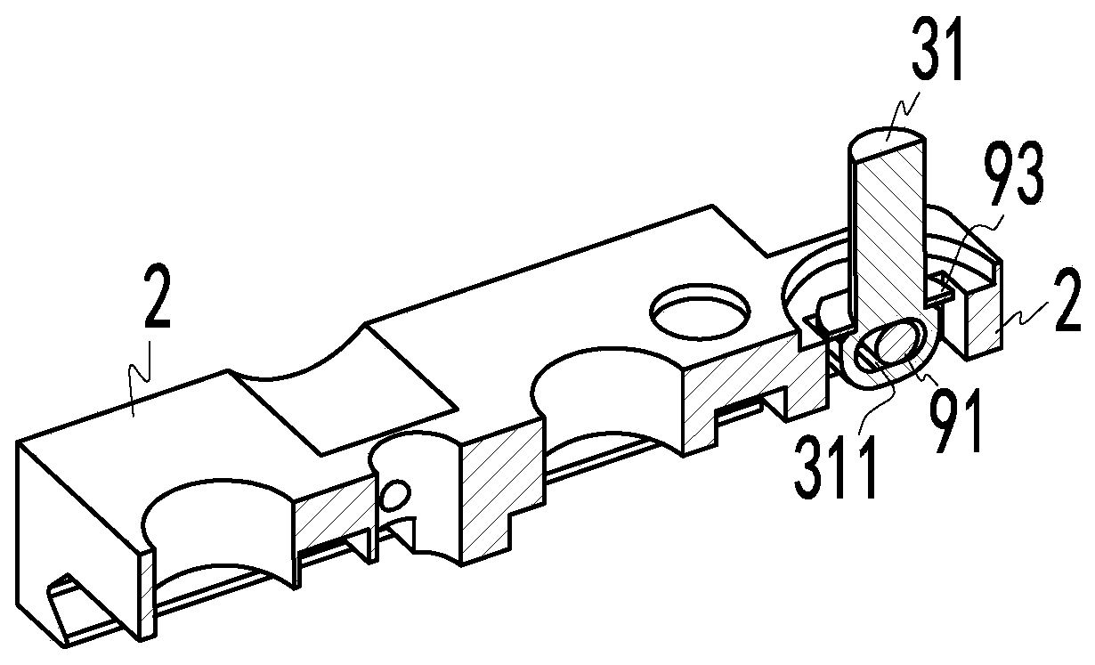
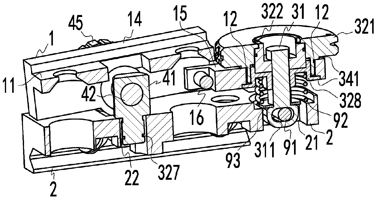
[0057] Such as figure 1 with figure 2 As shown, at least one embodiment of the present invention provides a connection structure for optical adjustment, which is used for the connection between the bracket body 1 and the bracket base 2, and can realize adjustment in a single direction (such as the up and down direction), which includes a first connecting column 31 and a handwheel device 32, the first connecting column 31 is used to connect the bracket seat 2, the handwheel device 32 is...


PUM


Abstract

The invention provides an adjusting support and a sighting telescope. The adjusting support comprises a support body, a support seat, a connecting structure and a hinged structure. The connecting structure comprises a first connecting column and a hand wheel device which are connected with the support body and the support seat correspondingly. The hand wheel device is arranged on the first connecting column in a sleeving manner, and the hand wheel device can do reciprocating motion in the length direction of the first connecting column so as to drive the support body to achieve up-and-down adjustment. The hinged structure comprises a second connecting column and a first adjusting shaft which are connected with the support body and the support seat correspondingly. The first adjusting shaftis arranged on the second connecting column in penetrating manner through threaded engagement so as to drive the support body to achieve left-and-right adjustment. The two kinds of adjustment do notinterfere with each other and can adapt to occasions with different adjustment requirements. The adjusting support can also be used for modifying an existing sighting telescope, and the defect that the adjusting stroke of the existing sighting telescope is short is overcome so as to avoid waste of the existing sighting telescope. The sighting telescope comprises the above adjusting support. Through the above adjusting support, adjustment, in the up-and-down direction and the left-and-right direction, of the sighting telescope can be achieved, the sighting telescope can omit an inner adjustingstructure, and the structure can be simplified.

Description

technical field [0001] The invention relates to the technical field of aiming devices, in particular to a connection structure for optical adjustment, a hinge structure, an adjustment bracket and a sight. Background technique [0002] At present, the reticle center of the scope is set on the reticle, and the reticle is installed inside the lens barrel. Therefore, the gun is calibrated by adjusting the internal adjustment mechanism of the scope, that is, the distance compensation knob located directly above the lens barrel and the The windage compensation knob on the side of the lens barrel is realized. The distance compensation knob can make the lens barrel reciprocate in the vertical direction, and the windage compensation knob can make the lens barrel reciprocate in the horizontal direction. Adjust the distance compensation knob or windage compensation knob according to the actual application, so that the reticle center moves along the up, down, left, and right directions,...

Claims


Application Information

Patent Timeline
Patent Type & Authority Applications(China)
IPC IPC(8): F41G1/26
CPCF41G1/26
Inventor 姜建勇
Owner ZHUHAI MEFO OPTICAL INSTR CO LTD
Why Eureka
Try Eureka