
Detection tool for detecting deep hole length of gear shaft

A gear shaft and deep hole technology is applied in the field of inspection tools for detecting the length of the deep hole of the gear shaft. simple structure

Pending Publication Date: 2019-08-16
JIANGSU PACIFIC GEAR DRIVE CO LTD +1
View PDF0 Cites 1 Cited by
  • Summary
  • Abstract
  • Description
  • Claims
  • Application Information

AI Technical Summary

Problems solved by technology

[0003] At present, there are mainly the following three methods for measuring the deep hole of the gear shaft; 1) Direct measurement method: use a vernier depth caliper to directly measure the depth of the deep hole. The accuracy of the data is too low; 2), indirect measurement method: use a profiler to measure the depth of the adjacent hole connected to the deep hole, and subtract the length of the adjacent hole from the total length of the gear shaft to get the length of the deep hole
However, the profiler has high requirements on the inspection conditions, and the detection efficiency is very low, so it cannot be used for on-site inspection of mass production; 3), special inspection tool method: the length of the inspection tool is the standard value, and then the dial indicator is installed to measure the deep hole deep
With this method, the measurement point of the bottom of the deep hole is usually taken at the center line of the slope at the bottom of the deep hole. Due to the large tolerance of the slope angle, it has a great influence on the measured value of the depth of the deep hole, so the measurement error is also large

Method used


Image

  • Detection tool for detecting deep hole length of gear shaft
  • Detection tool for detecting deep hole length of gear shaft
  • Detection tool for detecting deep hole length of gear shaft

Examples


Embodiment

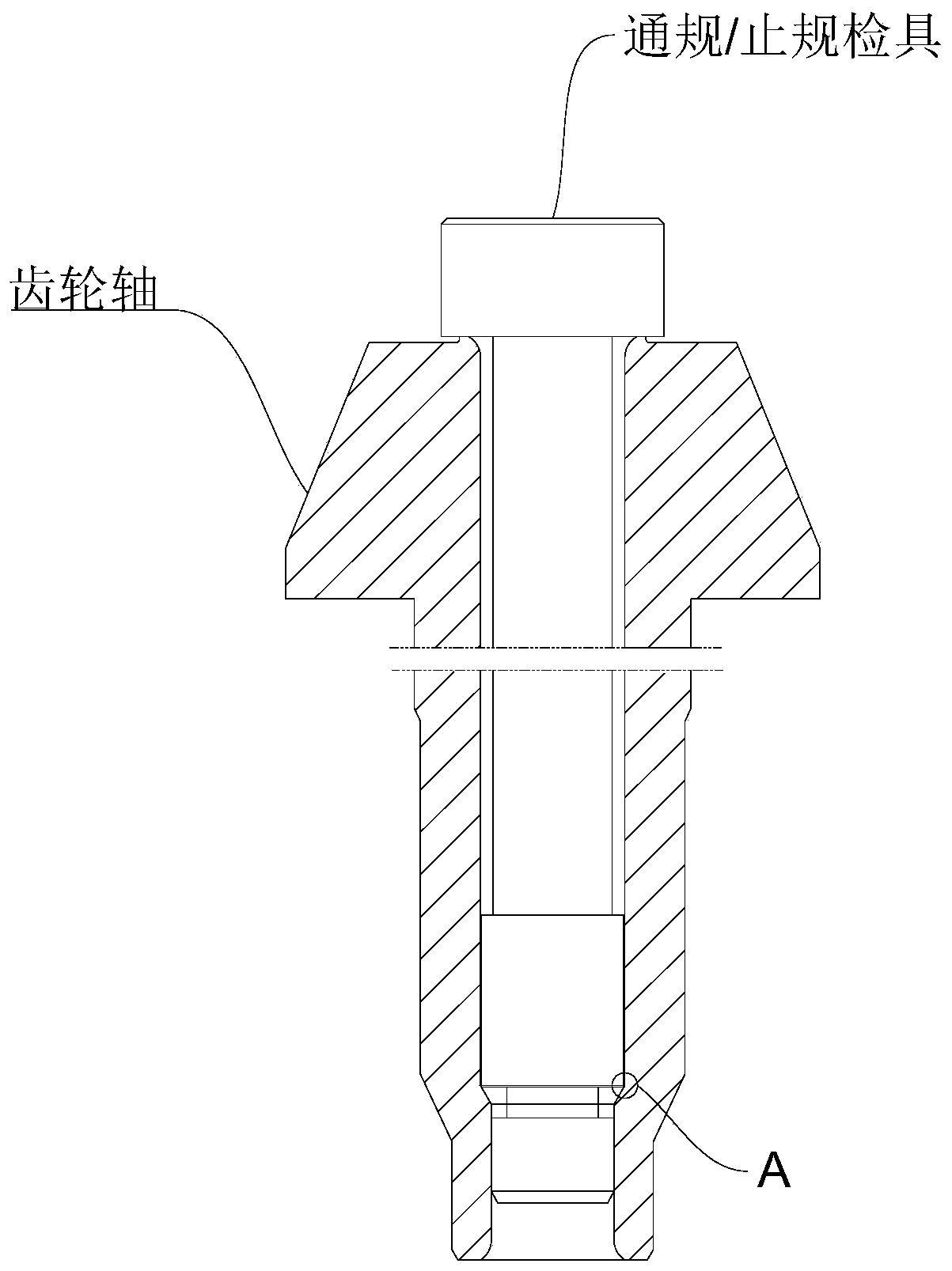
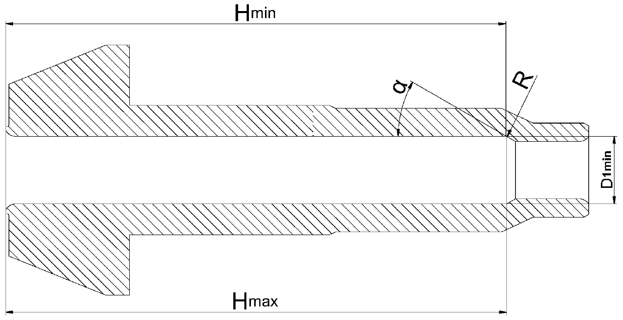
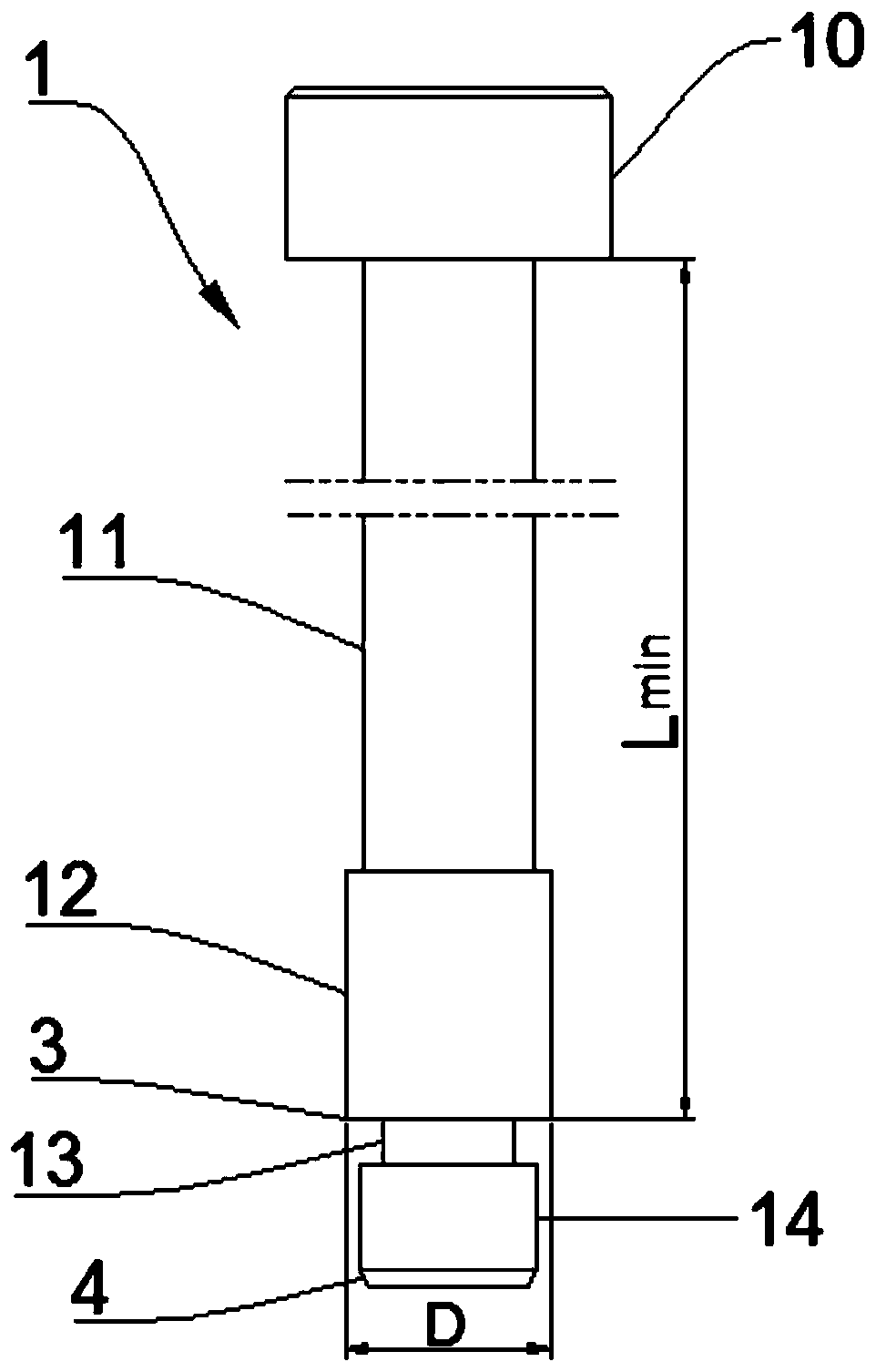
[0035] Such as figure 1 As shown, the present embodiment provides a checker 100 for detecting the length of a deep hole of a gear shaft, such as figure 2 As shown, it is used to detect whether the length of the deep hole in the gear shaft with adjacent holes is qualified. The checking tool 100 for detecting the length of the deep hole of the gear shaft includes a cylindrical through-gauge checking tool 1 and a cylindrical stop-gauge checking tool 2 . Such as image 3 As shown, the above-mentioned through-gauge inspection tool 1 is composed of an integrally formed through-end reference part 10 , a through-end first neck 11 , a through-end upper positioning part 12 , a through-end second neck 13 and a through-end lower positioning part 14 . Such as Figure 4 As shown, the above-mentioned stop gauge inspection tool 2 is composed of an integrally formed stop reference part 20 , a stop first neck 21 , a stop upper positioning part 22 , a stop second neck 23 and a stop lower pos...


PUM


Abstract

The invention belongs to the technical field of gear shaft hole depth detection equipment, and particularly relates to a detection tool for detecting a deep hole length of a gear shaft. The detectiontool comprises cylindrical go-gauge detection tool and non-go-gauge detection tool which are used in a matched mode; the go-gauge detection tool is composed of a go-end reference part, a go-end firstneck part, a go-end upper positioning part, a go-end second neck part and a go-end lower positioning part which are formed integrally; and the non-go-gauge detection tool comprises a non-go-end reference part, a non-go-end first neck part, a non-go-end upper positioning part, a non-go-end second neck part and a non-go-end lower positioning part which are formed integrally. The detection tool is simple in structure and convenient to use; the corresponding go-gauge detection tool and non-go-gauge detection tool can be made according to the deep hole length and the adjacent hole diameter designedfor the gear shaft; rapid batch detection can be carried out on the gear shaft of the type, so that whether the deep hole depth of the produced gear shaft meets the design requirement or not is determined; the practice proves that the go-gauge detection tool and the non-go-gauge detection tool are matched well; and the detection precision completely meets the industrial requirements.

Description

technical field [0001] The invention belongs to the technical field of gear shaft hole depth detection equipment, and in particular relates to a checking tool for detecting the length of a deep hole of a gear shaft. Background technique [0002] The gear shaft is a common shaft-hole mechanical part, and most of them adopt the integrated structure of the deep hole and the gear. The effective depth of the deep hole is an important measurement element of the gear shaft. [0003] At present, there are mainly the following three methods for measuring the deep hole of the gear shaft; 1) Direct measurement method: use a vernier depth caliper to directly measure the depth of the deep hole. 2) Indirect measurement method: measure the depth of the adjacent hole connected to the deep hole with a profiler, and subtract the length of the adjacent hole from the total length of the gear shaft to obtain the length of the deep hole. However, the profiler has high requirements on the inspect...

Claims


Application Information

Patent Timeline
IPC IPC(8): G01B5/18G01B5/02
CPCG01B5/18G01B5/02
Inventor 徐树存臧扬夏宇
Owner JIANGSU PACIFIC GEAR DRIVE CO LTD
Learn More