

Hair grinding equipment
A hair and equipment technology, applied in the field of grinding instruments, can solve the problems of long grinding time, poor safety, poor grinding effect, etc., and achieve the effect of avoiding sample leakage and easy loading.
- Summary
- Abstract
- Description
- Claims
- Application Information
AI Technical Summary
Problems solved by technology
Method used
Image

Examples
Embodiment
[0041] A hair grinding device, comprising:
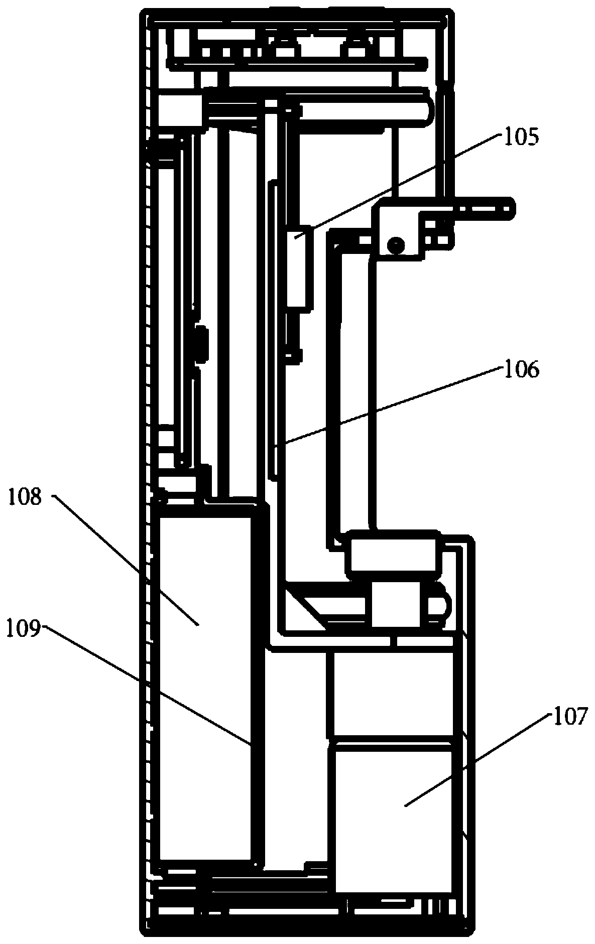
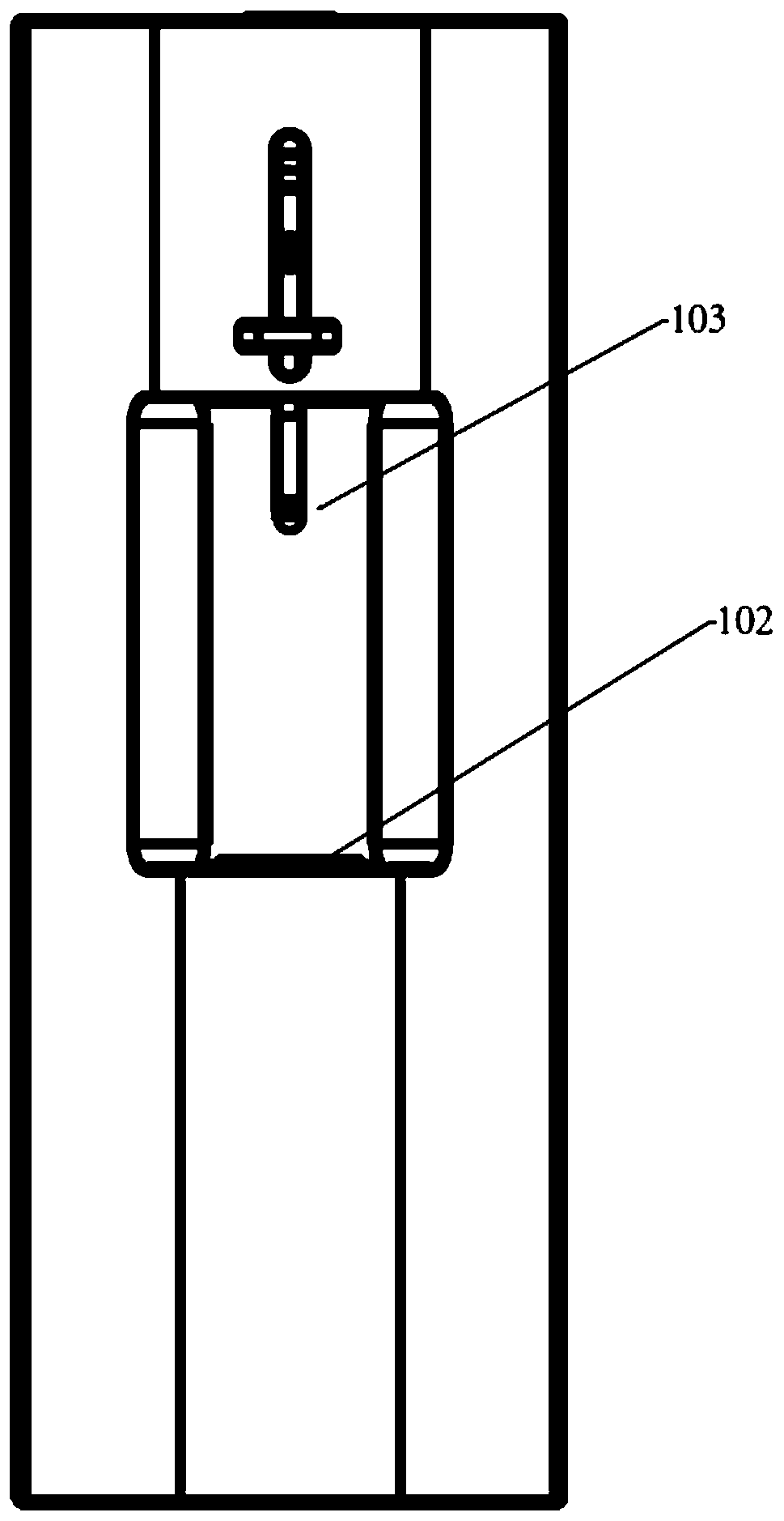
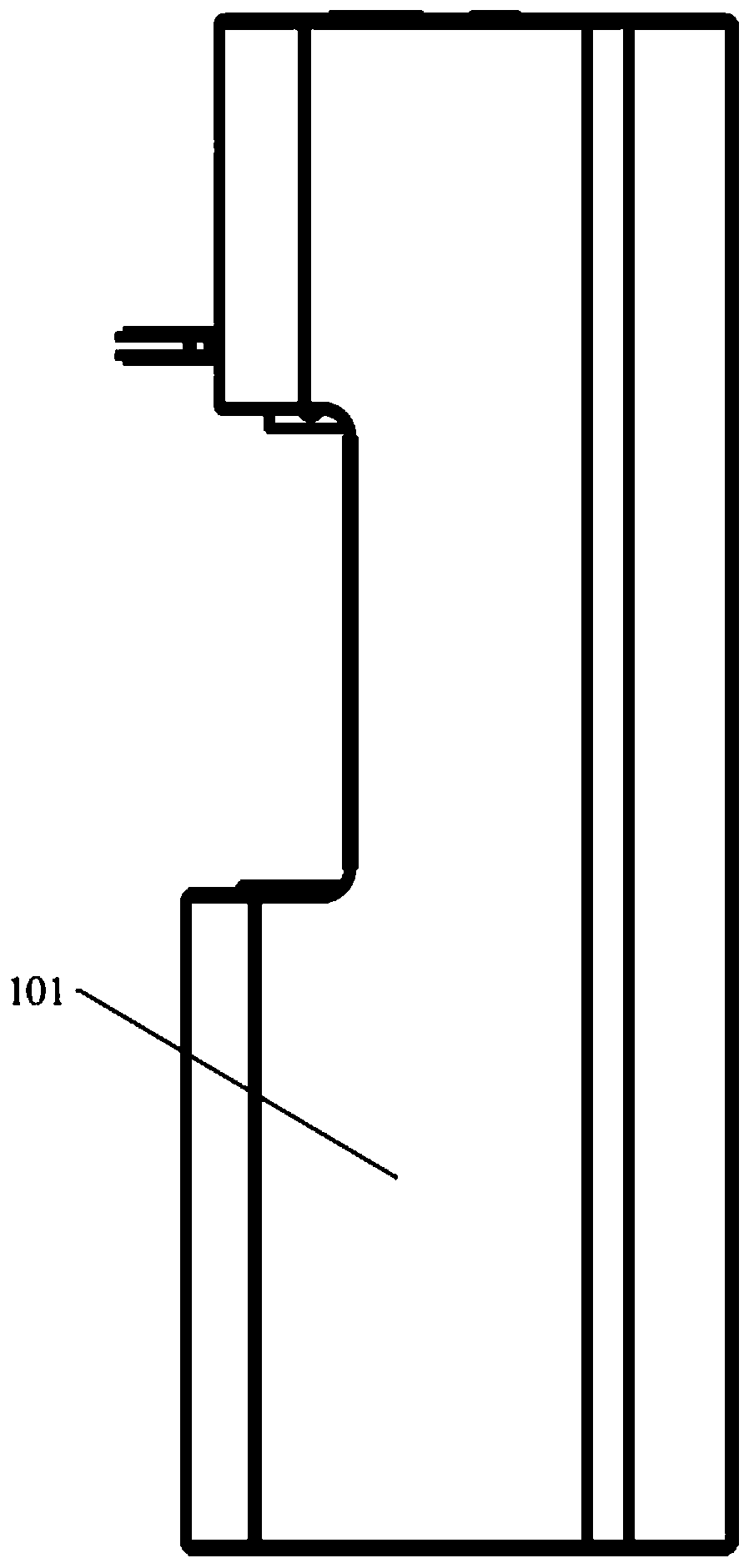
[0042] Grinder 1, such as Figure 1-6 As shown: it includes a main machine shell 101, a connecting assembly arranged on the main machine shell 101 for connecting the grinding head 2, and a drive assembly and a switch assembly for driving the grinding assembly to run. The connecting assembly includes a rotatable Grinding tube placement groove 102, grinding head sleeve 103 connected to grinding head 2, and push-pull piece 104 that drives grinding head sleeve 103 to rise and fall;
[0043] Grinding head 2: including an upper handle 201 detachably connected to the grinding head sleeve 103, and a first grinding sheet 202 fixed at the bottom end of the upper handle 201;
[0044] Grinding tube 3: includes a grinding tube main body 301 detachably connected to the grinding head 2, a grinding tube fixing base 303 fixed on the outside of the bottom of the grinding tube main body 301 to match the grinding tube placement groove 102, and arrange...
PUM
 Abstract
Description
Claims
Application Information