
Secondary electron detector, charged particle optical imaging device and detection method

A technology of secondary electron and detection method, which is applied in the field of scanning electron microscopy, can solve problems such as image distortion, and achieve the effect of improving precision and clarity

Active Publication Date: 2020-09-04
SHANGHAI PRECISION MEASUREMENT SEMICON TECH INC
View PDF9 Cites 0 Cited by
  • Summary
  • Abstract
  • Description
  • Claims
  • Application Information

AI Technical Summary

Problems solved by technology

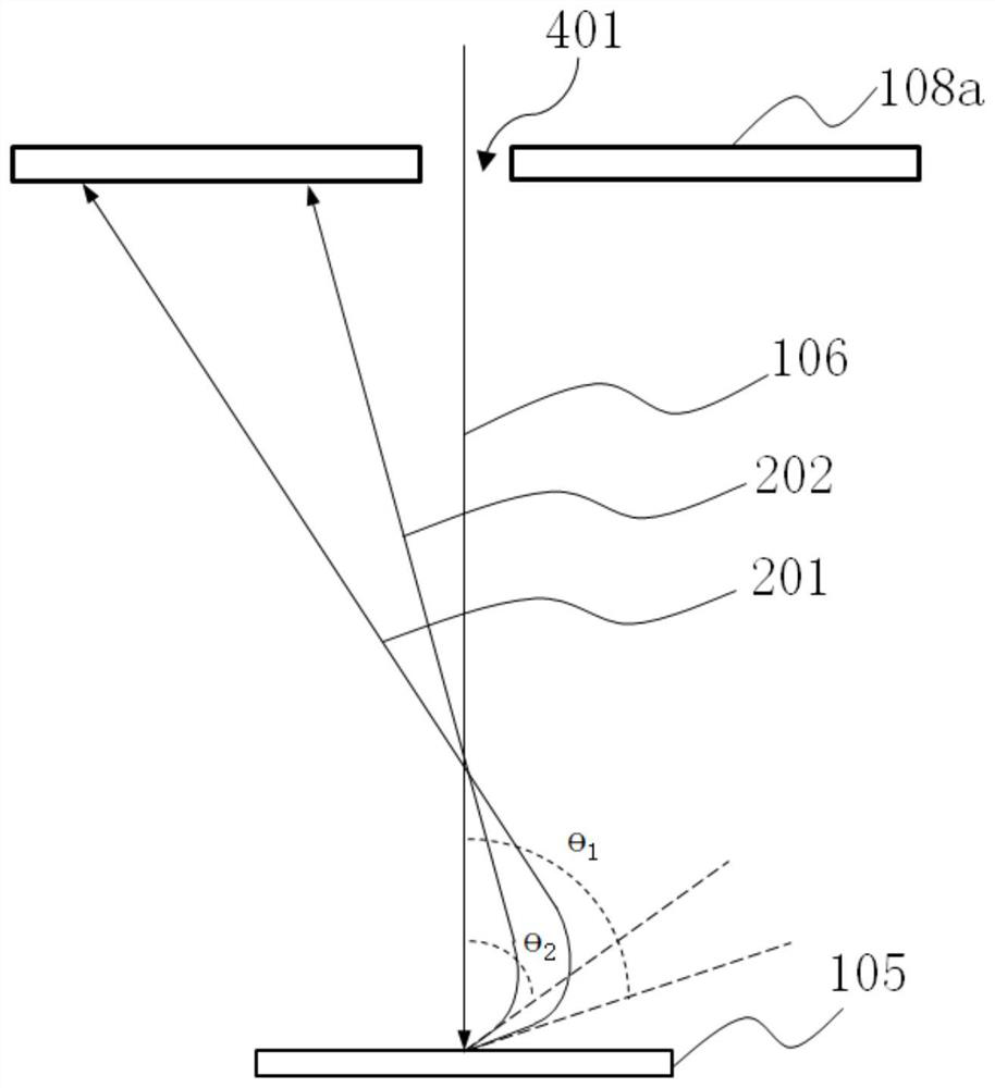
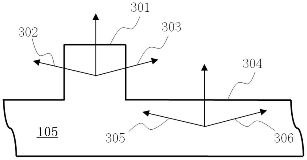
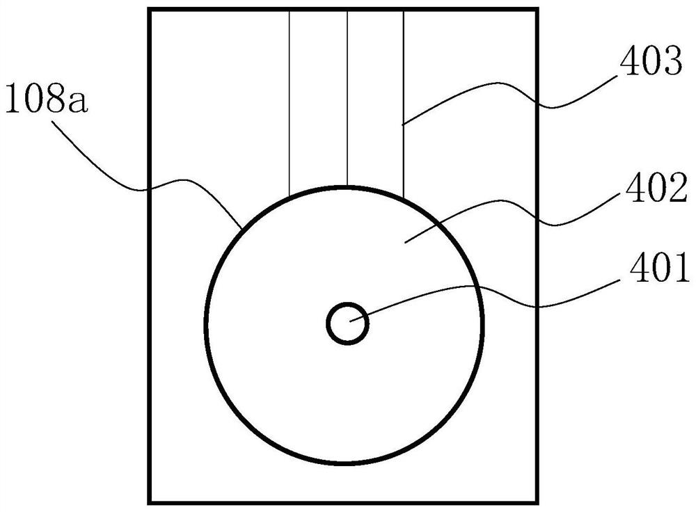
[0007] One of the objectives of the present invention is to disclose a secondary electron detector, which can overcome the defect of pattern distortion caused by the characteristics of the sample surface such as particles, bumps and edges, and realize the effective implementation of secondary electrons at different exit angles. detection to improve the detection effect on samples; at the same time, the invention also discloses a charged particle optical imaging device, and discloses a detection method for charged particle detection using a secondary electron detector

Method used


Image

  • Secondary electron detector, charged particle optical imaging device and detection method
  • Secondary electron detector, charged particle optical imaging device and detection method
  • Secondary electron detector, charged particle optical imaging device and detection method

Examples


Embodiment 1

[0048] combine Figure 5 and refer to Figure 4 As shown, this embodiment discloses a secondary electron detector. The secondary electron detector is used to receive the secondary electrons (Secondary Electrons, SE) generated by the incident charged particle beam bombarding the surface of the sample 105, without receiving back scattered electrons (Back Scattered Electron, BSE), and through the two The signal amplification circuit and the analog-to-digital conversion circuit connected to the sub-electron detector present the microscopic topography of the surface of the sample 105 on the display device.

[0049] Based on the scanning electron microscope (SEM) assembled and formed by the secondary electron detector, the surface of the physical sample, microelectronic devices such as micron-scale and nano-scale semiconductor devices, optical integrated devices, microwave devices, quantum devices, or cell tissues are observed. The surface topography of the sample can be effective...

Embodiment 2

[0060] With reference Figure 6 Another modified embodiment of a secondary electron detector of the present invention is shown. The main difference between this embodiment and Embodiment 1 is that in the secondary electron detector disclosed in this embodiment, the circular detection area is radially divided into at least two isolated and fan-shaped first sub-detection areas according to the azimuth angle. , and further specifically, the circular detection area is divided into at least two annular first sub-detection areas that are equally divided and isolated.

[0061] The secondary electron detector is divided into several first sub-detection areas according to the azimuth separation, that is, the first sub-detection area 601 , the first sub-detection area 602 , the first sub-detection area 603 and the first sub-detection area 604 . Those skilled in the art can reasonably predict that the secondary electron detector can also be divided into two, three, five or more first su...

Embodiment 3

[0067] With reference Figure 7 Another modified embodiment of a secondary electron detector of the present invention is shown. The main difference between this embodiment and the secondary electron detector shown in Embodiment 1 and / or Embodiment 2 is that, in this embodiment, the central hole 401 is provided with a number of mutually isolated circular detection areas, and The radially outward portion of the ring detection area forms a second sub-detection area that is radially divided into at least two isolated fan-shaped sub-detection areas according to the azimuth angle. The circular detection area radially outward forms the second sub-detection area formed by radial division according to the azimuth angle, and the number may be two, three, five or any other number.

[0068] In particular, it should be noted that, Figure 7 It is only an exemplary solution of a secondary detector disclosed in this embodiment. As another reasonable modification, one or more annular detec...


PUM


Abstract

The invention discloses a secondary electron detector, charged particle optical imaging equipment comprising the secondary electron detector, and a detection method. According to the secondary electron detector, at least three mutually isolated circular ring detection zones are formed outwards in the radial direction of the symmetric center of a detection zone formed by the secondary electron detector, and secondary electrons emitted from the surface of a sample can be received through the circular ring detection zones. According to the secondary electron detector and the charged particle optical imaging equipment disclosed by the invention, the accuracy of characterizing the intrinsic morphology of the sample for the sample on the basis of a detection image formed by secondary electron detection is improved; the defect of image distortion caused by characteristics of surface particles, protrusions, edges and the like of the sample is overcome; and the detection effect of the secondaryelectrons with different azimuth angles is achieved.

Description

technical field [0001] The present invention relates to the technical field of scanning electron microscopy, in particular to a secondary electron detector for detecting secondary electrons, a charged particle optical imaging device based on the secondary electron detector, and a secondary electron detector Detection method for charged particle detection. Background technique [0002] Scanning Electron Microscope (SEM), or "SEM" for short, is a charged particle optical device that uses secondary electron signal imaging to observe the surface morphology of samples. The scanning electron microscope is a charged particle optical device used for microscopic morphology observation between the transmission electron microscope (TEM) and the optical microscope. [0003] Such as figure 1 As shown, the electron source 101 of the scanning electron microscope (with reference Figure 4 As shown), the high-energy electron beam 106 emitted vertically downwards and penetrates the central...

Claims


Application Information

Patent Timeline
Patent Type & Authority Patents(China)
IPC IPC(8): G01N23/2251
CPCG01N23/2251
Inventor 张旭
Owner SHANGHAI PRECISION MEASUREMENT SEMICON TECH INC
Learn More