Rotor crack fault detection method based on interval control strategy
A rotor crack and interval control technology, which is applied in the field of aero-engines, can solve the problem of low success rate of rotor cracks and achieve the effect of improving the success rate
- Summary
- Abstract
- Description
- Claims
- Application Information
AI Technical Summary
Problems solved by technology
Method used
Image

Examples
specific Embodiment approach 1
[0023] Specific implementation mode one: combine figure 1 To illustrate this embodiment, the rotor crack fault detection method based on the interval control strategy given in this embodiment specifically includes the following steps:
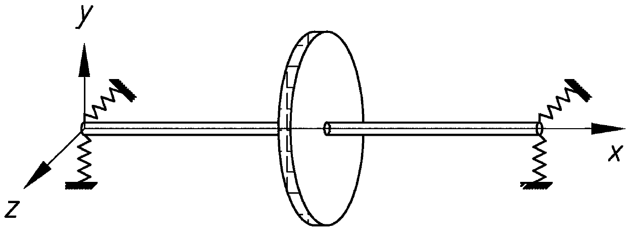
[0024] Step 1. Select the low-pressure part of the dual-rotor structure of the aero-engine to establish a single-rotor system model, and establish a coordinate system; the coordinate system takes the endpoint where the rotor coincides with the center of mass of the aircraft as the origin o, and is firmly connected with the aircraft body. The rotor coordinate system is also the aircraft body Coordinate system, the x-axis of the coordinate system is parallel to the longitudinal axis of the aircraft fuselage, pointing to the forward direction of the aircraft, the y-axis is located in the symmetry plane of the aircraft, perpendicular to the ox-axis, pointing directly above the aircraft, and the oz-axis forms with the ox-axis and y-axis right-handed...
specific Embodiment approach 2
[0031] Specific embodiment 2: The difference between this embodiment and specific embodiment 1 is that the rotor system dynamics model described in step 3 is specifically:
[0032]
[0033] exist figure 2 In the rotor system model shown, considering a crack at the packing and considering a constant excitation in the y direction, a rotor system dynamics model such as formula (1) is established. Among them, m is the mass of the turntable, c is the damping, and c=2ξmω, ξ is the damping ratio; ω is the speed, △k is the crack stiffness, indicating the influence of the crack depth on the stiffness of the rotating shaft; k is the support stiffness of the rotor system; y is The y-axis coordinate of the center of mass of the turntable, are the first-order derivative and second-order derivative of y respectively; t is time, z is the z-axis coordinate of the center of mass of the turntable; e is the distance from the eccentricity of the turntable to the center of mass of the turntabl...
specific Embodiment approach 3
[0035] Embodiment 3: This embodiment differs from Embodiment 2 in that the specific process of converting the rotor system dynamics model into a vibration response equation described in step 4 includes:
[0036] Step 41. Dimensionless the rotor system dynamics model:
[0037]
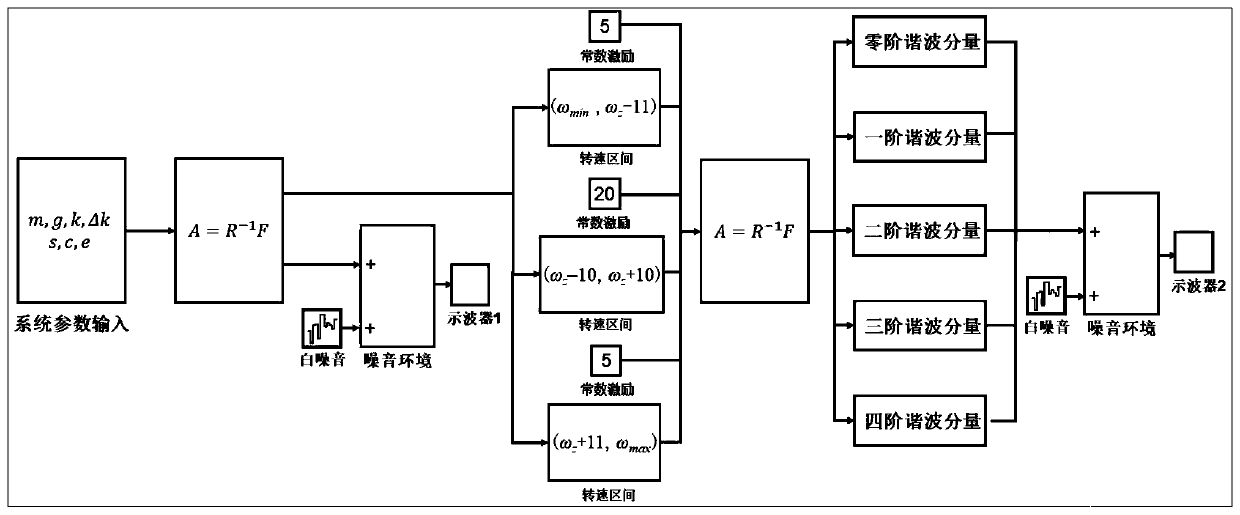
[0038] Among them, δ, s, τ, K, Y, Z are intermediate variables; ω n is the natural frequency of the system; F represents the influence of unbalanced excitation force, G represents the influence of gravity, H is the influence of external constant excitation, and its numerical value represents the multiple of external constant excitation relative gravity; in the rotor system model among the present invention, A constant excitation can be applied by electromagnetic force. The electromagnetic field environment is built on the rotor system, and the electromagnetic force is used to create a simulated overweight environment, so that constant excitation appears on the rotor system, resulting in the effect o...
PUM
 Abstract
Description
Claims
Application Information
 - R&D
- Intellectual Property
- Life Sciences
- Materials
- Tech Scout
- Unparalleled Data Quality
- Higher Quality Content
- 60% Fewer Hallucinations
Browse by: Latest US Patents, China's latest patents, Technical Efficacy Thesaurus, Application Domain, Technology Topic, Popular Technical Reports.
© 2025 PatSnap. All rights reserved.Legal|Privacy policy|Modern Slavery Act Transparency Statement|Sitemap|About US| Contact US: help@patsnap.com