Bonding device and bonding method

A bonding and equipment technology, applied in the manufacturing of electrical components, electrical solid-state devices, semiconductor/solid-state devices, etc., can solve the problems of inconvenient electrical wiring, complex structure, and low yield in the vision system

Active Publication Date: 2019-08-16
SHANGHAI MICRO ELECTRONICS EQUIP (GRP) CO LTD
View PDF8 Cites 2 Cited by
  • Summary
  • Abstract
  • Description
  • Claims
  • Application Information

AI Technical Summary

Problems solved by technology

[0004] The purpose of the present invention is to provide a bonding equipment and bonding method to solve the problems of low yield, complex structure and inconvenient electrical wiring of the visual system in the existing technology.

Method used


Image

  • Bonding device and bonding method
  • Bonding device and bonding method
  • Bonding device and bonding method

Examples


Embodiment 1

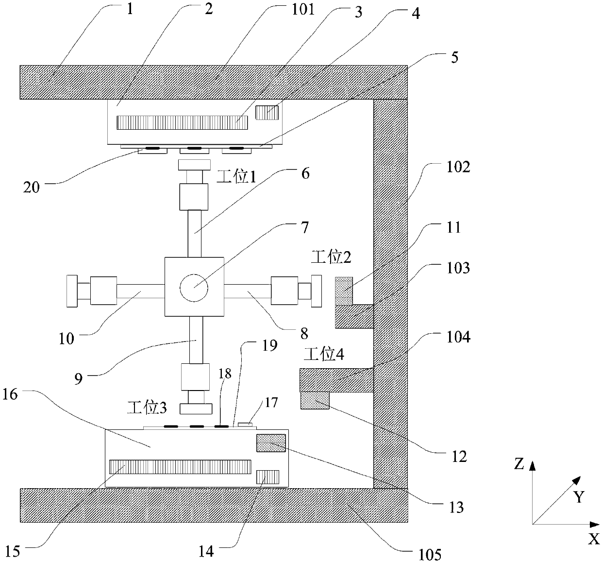
[0066] refer to figure 1 , which is a schematic structural diagram of the bonding equipment in Embodiment 1 of the present invention, the bonding equipment includes a supply motion table 2, a transmission system, a bonding motion table 16 and an alignment measurement system; the transmission system includes a rotation unit 7 and A plurality of chip bonding units uniformly arranged on the rotating unit 7, the rotating unit 7 drives the chip bonding unit to go back and forth between the chip picking station, the chip position measuring station and the chip bonding station in sequence The described supply motion table 2 carries some first chips, and the bonding motion table 16 carries some second chips; the chip bonding unit is used to pick up the first chip from the supply motion table 2, and The first chip is transferred and handed over to the corresponding second chip; and the alignment measurement system includes a first alignment measurement unit 11, a second alignment measu...

Embodiment 2

[0113] The chip alignment mark 18 is located on the side of the second chip facing away from the bonding motion table 16, and the chip identification mark can be located on the side of the first chip facing the supply motion table, or can also be located on the back side of the first chip. On the side facing the feeding motion table, when the chip identification mark is located on the side of the first chip facing away from the feeding motion table, the first alignment measurement unit 11 and the third alignment measurement unit 13 are the back side Align the measurement system. Specifically, see 14, Figure 14 It is a schematic structural diagram of the bonding equipment in Embodiment 2 of the present invention. Compared with Embodiment 1, the structural composition of the bonding equipment is different in that: the first alignment measurement unit 11 is a backside alignment measurement system, and its light source can be An infrared light source is used, which can penetrate...


PUM


Abstract

The invention provides a bonding device and a bonding method. The bonding device comprises a supply motion platform, a transmission system, a bonding motion platform and an alignment measurement system. The functions of handover, transmission and measurement of a first chip are continuously achieved by adopting the supply motion platform, the transmission system, the bonding motion platform and the alignment measurement system, the circulation time of a single chip is reduced, the bonding of the first chip and a corresponding second chip on the substrate can be effectively completed, and the yield is improved. Further, the size of the bonding device is compact, the structure is simpler, the alignment measurement system is arranged on the frame and the bonding motion platform, and electrical wiring is more convenient; and moreover, by adopting the bonding method, the position of the alignment measurement system is pre-calibrated in advance, and the bonding of the first chip on the supply motion platform and the corresponding second chip on the bonding motion platform is achieved.

Description

technical field [0001] The invention relates to the field of semiconductor manufacturing, in particular to a bonding device and a bonding method. Background technique [0002] Chip bonding is a key process step in the packaging process of semiconductor devices. The process of chip bonding is to carry out a series of treatments such as bonding and plastic sealing of the diced bare chips attached to the blue film to form usable semiconductor devices. device. With the wide application of semiconductor devices, chip bonding equipment must complete chip bonding operations efficiently, accurately, stably and reliably. [0003] An existing bonding equipment includes a transposition mechanism, which can make two pick-up mechanisms circulate and rotate between the pick-up position and the transfer position respectively, so as to ensure the continuous progress of pick-up and transfer, and improve production efficiency. Its disadvantages are that the lens is installed on the rotating...

Claims


Application Information

Patent Timeline
Patent Type & Authority Applications(China)
IPC IPC(8): H01L21/67H01L21/68H01L21/60H01L21/66
CPCH01L21/67121H01L21/68H01L22/12H01L24/80
Inventor 刘育
Owner SHANGHAI MICRO ELECTRONICS EQUIP (GRP) CO LTD
Why Eureka
Try Eureka