
Method and system for distributing quantum keys to terminals in transformer area

A quantum key distribution and quantum key technology, applied in the field of quantum key distribution, can solve the problems of low security, increase the amount of key generation, unable to meet a large number of keys for power distribution terminals, etc., to improve security. properties, achieve effective utilization, and achieve the effect of secure encrypted transmission

Active Publication Date: 2019-08-16
BEIJING SMARTCHIP MICROELECTRONICS TECH COMPANY +3
View PDF12 Cites 2 Cited by
  • Summary
  • Abstract
  • Description
  • Claims
  • Application Information

AI Technical Summary

Problems solved by technology

[0004] Based on this, the inventors of the present application found that in the prior art, the terminal devices in a station area use the same quantum key for data encryption and decryption, which has low security
To improve security and meet the requirements of terminal devices in a station area using different quantum keys for data encryption and decryption, it is necessary to increase the amount of key generation. However, the current encryption machine storage limit and the quantum key distribution Restrictions, unable to meet the needs of a large number of keys required by power distribution terminals

Method used


Image

  • Method and system for distributing quantum keys to terminals in transformer area
  • Method and system for distributing quantum keys to terminals in transformer area
  • Method and system for distributing quantum keys to terminals in transformer area

Examples


Embodiment 1

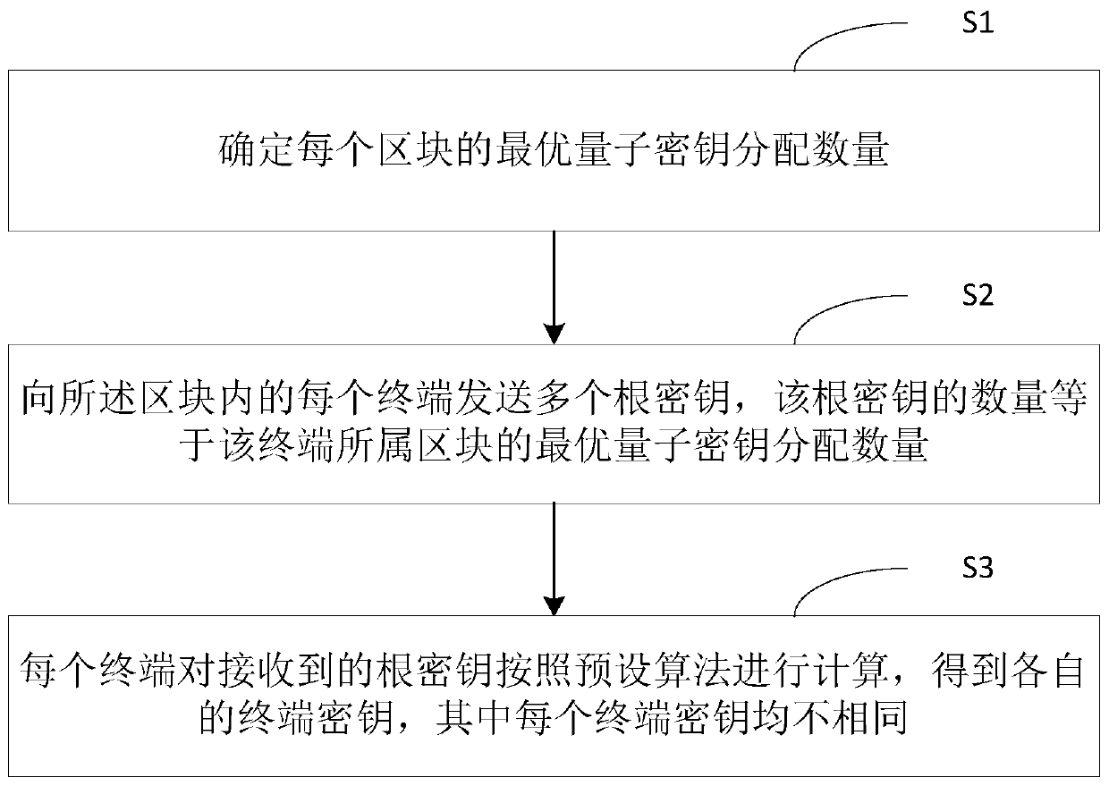
[0024] Such as figure 1 As shown, it is a flowchart of a method for distributing quantum keys to terminals in a station area according to a preferred embodiment of the present invention. In this embodiment, the station area is divided into the following according to the density of terminals in the station area. A plurality of blocks, a station area includes a plurality of blocks, a block includes a plurality of terminals. In the power system, the station area is the power supply range or area of ​​a transformer, and the terminal equipment can include concentrators, meter collectors, etc.

[0025] The method for distributing quantum keys to terminals in the station area provided by this embodiment includes: steps S1-S4.

[0026] Step S1, determine the optimal quantity of quantum key distribution for each block.

[0027] Before step S1, it may further include: step S0, dividing the station area into the plurality of blocks according to the density of terminals in the station a...

Embodiment 2

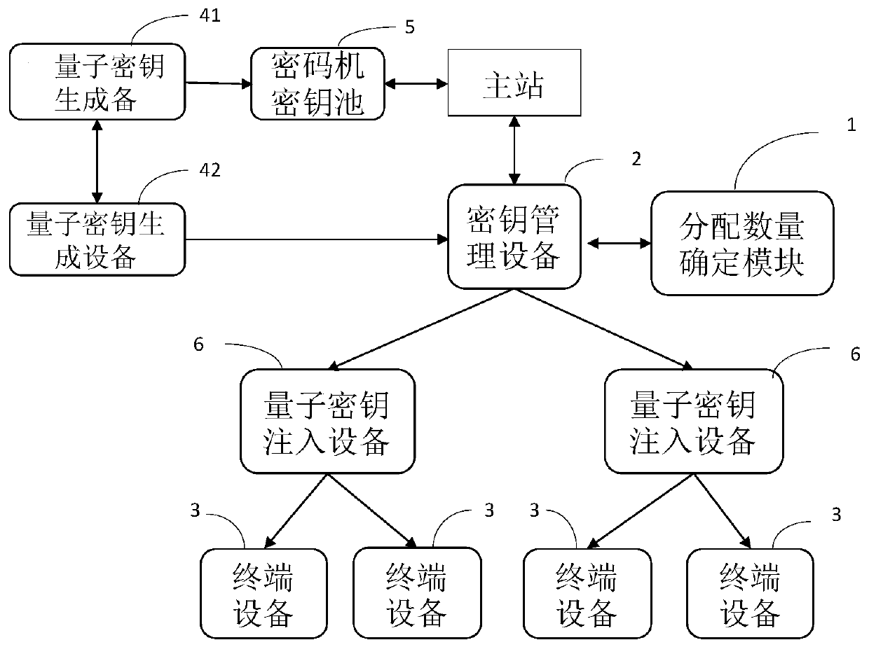
[0073] Such as figure 2 As shown, it is a schematic structural diagram of a system for distributing quantum keys to terminals in a station area according to a preferred embodiment of the present invention. The system for distributing quantum keys to terminals in a station area provided by this embodiment is used to realize The method in Embodiment 1 includes: a distribution quantity determination module 1 , a key management device 2 and a terminal 3 . The system provided in this embodiment may also include a quantum key generation device 4 .

[0074] The distribution number determination module 1 is used to determine the optimal distribution number of quantum keys for each block.

[0075] The allocation quantity determination module 1 is further configured to divide the station area into the multiple blocks according to the density of terminals in the station area.

[0076] The key management device 2 is respectively connected with the distribution number determination modu...


PUM


Abstract

The invention discloses a method and a system for distributing quantum keys to terminals in a transformer area, the transformer area comprises a plurality of blocks, and the method comprises the following steps: determining the optimal quantum key distribution quantity of each block; sending a plurality of root keys to each terminal in the block, wherein the number of the root keys is equal to theoptimal quantum key distribution number of the block to which the terminal belongs; and enabling each terminal to calculate the received root key according to a preset algorithm to obtain a respective terminal key, wherein the terminal keys are different. According to the method and the system for carrying out quantum key distribution on the terminals in the transformer area provided by the embodiment of the invention, the secure encryption transmission of the power distribution and utilization service data can be realized, the effective utilization of the quantum keys is realized, the security is improved, and the demand of a large number of keys required by the power distribution and utilization terminal can be met.

Description

technical field [0001] The present invention relates to distribution of quantum keys, in particular to a method and system for distributing quantum keys to terminals in a station area. Background technique [0002] With the construction of smart grid and the continuous development of terminal technology, the security and confidentiality requirements of terminal systems are also getting higher and higher. Due to its unmeasurable and non-cloning principles, quantum keys have higher security and have gradually replaced traditional keys in smart grids. [0003] In the smart grid, the master station side of the existing scheme generates a quantum key through a quantum key generation device and stores it in the cipher machine of the master station device. The master station uses the quantum key in the cipher machine to encrypt the data, and sends the encrypted data to the terminal, or uses the quantum key in the cipher machine to decrypt the received data. On the terminal side, ...

Claims


Application Information

Patent Timeline
Patent Type & Authority Applications(China)
IPC IPC(8): H04L9/08H04L9/14H04L9/06
CPCH04L9/0852H04L9/0858H04L9/14H04L9/0822H04L9/0866H04L9/0869H04L9/0643
Inventor 王东山高建李温静王立城霍超白晖峰苑佳楠张丽郝佳恺
Owner BEIJING SMARTCHIP MICROELECTRONICS TECH COMPANY
Learn More