Skewering material cutting and skewering mold

A mold and trough technology, which is applied in the field of string cutting through molds, can solve the problems of low production efficiency and complicated operation, and achieve the effect of improving production efficiency and reducing the amount of preparation work.

Pending Publication Date: 2019-08-20
青岛国易食品科技有限公司
View PDF8 Cites 0 Cited by
  • Summary
  • Abstract
  • Description
  • Claims
  • Application Information

AI Technical Summary

Problems solved by technology

Although the stringing function can also be realized, the stringing material needs to be cut into blocks or strips that meet the standard size of stringing in advance, so the operation is more cumbersome and the production efficiency is low
[0003] Therefore, there is not yet a kind of stringing processing mold that integrates the functions of stringing cutting and stringing.

Method used


Image

  • Skewering material cutting and skewering mold
  • Skewering material cutting and skewering mold
  • Skewering material cutting and skewering mold

Examples


Embodiment 1

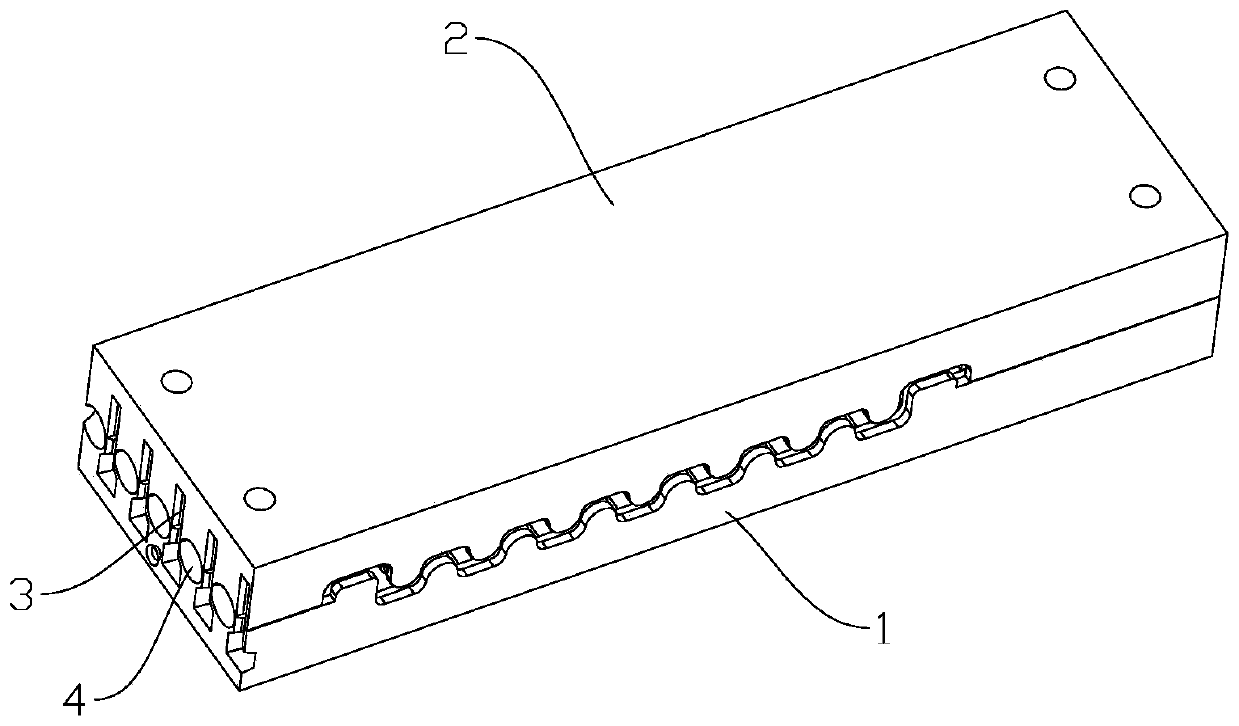
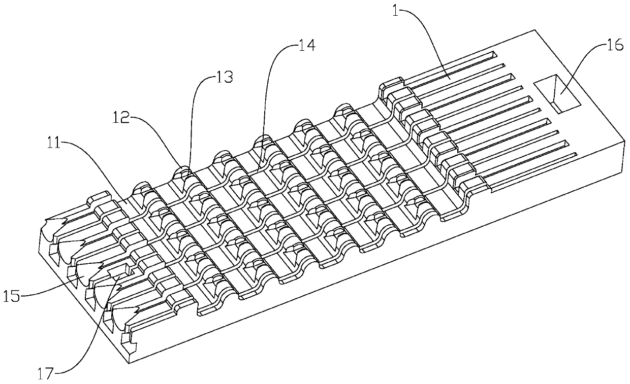
[0030] Such as Figure 1-3 As shown, the serial material in this embodiment cuts through the mold, including a first mold body 1 and a second mold body 2 that are fastened to each other.

[0031] On the first mold body 1, there are a plurality of first serial troughs 11 and first sign groove ribs 12 arranged in parallel at intervals along the transverse direction, and the first sign groove ribs 12 are longitudinally provided with first sign grooves 13; A mold body 1 is longitudinally spaced with a plurality of first feed grooves 14 arranged in parallel, and the first feed grooves 14 run through the rear end of the first mold body 1, the first stringing groove 11 and the first sign groove protrusion. Ridge 12, so that the first stringing chute 11 and the first signing groove rib 12 are separated, so that the first signing groove 13 and the first knife feeding groove 14 are arranged at intervals.

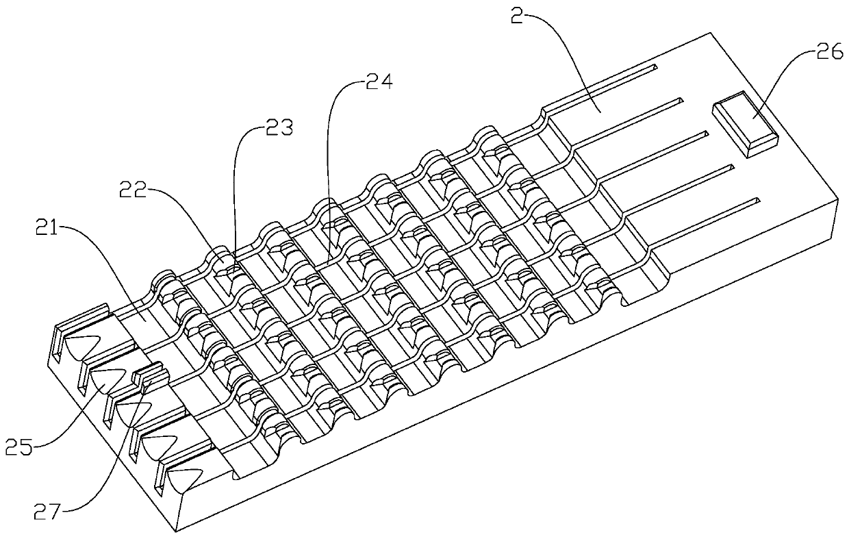
[0032] Correspondingly, on the second mold body 2, there are a plurality of para...

Embodiment 2

[0039] Such as Figure 4-6 As shown, the cross-cutting die of this embodiment has the same overall structure as that of the cross-cutting die in Embodiment 1. The difference between the two is:

[0040] In Embodiment 1, the first entry groove 14 and the second entry groove 24 do not pass through the front and rear ends of the first mold body 1 and the second mold body 2, and the first entry port 15 and the second entry port 25 are only arranged on the rear ends of the first mold body 1 and the second mold body 2 respectively, that is, the mold is only provided with the rear-end knife opening 3 and the rear-end entrance 4, and the cutter and the stick can only be drawn from one end of the mould. Enter.

[0041] In the second embodiment, the first infeed groove 14 and the second infeed groove 24 run through the front and rear ends of the first mold body 1 and the second mold body 2, respectively forming the front end knife edge 5 and the rear edge at the front and rear ends of th...


PUM


Abstract

The invention discloses a skewering material cutting and skewering mold. The mold comprises a first mold body, wherein first skewering material grooves and first skewer groove convex edges are transversely arranged on the first mold body alternatively, and first skewer grooves are formed in the first skewer groove convex edges; first knife feeding grooves are longitudinally formed in the upper edge of the first mold body, and penetrate through the rear end of the first mold body, the first skewering material grooves and the first skewer groove convex edges so as to segment the first skeweringmaterial grooves and the first skewer groove convex edges; and the first skewer grooves and the first knife feeding grooves are arranged alternatively. According to the mold, through arrangement of the knife feeding grooves and the skewer grooves on the mold body, skewering materials can be cut and separated while skewering is realized, so that cutting and skewering of the skewering materials arerealized by one-time action, the preparation workload in the earlier stage is reduced, and the production efficiency is improved to a certain extent.

Description

technical field [0001] The invention relates to the field of food processing machinery, in particular to a string cutting die. Background technique [0002] The working principle of the existing food stringing machine is roughly as follows: the stringing material to be stringed is placed on the mold manually, and after the mold is transported to the stringing station by the conveyor belt, the stringing mechanism pushes the stick into the mold, so that the stick Pass through the string material to complete the stringing action. Although the stringing function can also be realized, the stringing material needs to be cut into blocks or strips that meet the standard size of stringing in advance, so the operation is more cumbersome and the production efficiency is low. [0003] Therefore, there is not yet a kind of stringing processing mold integrating the functions of stringing cutting and stringing. Contents of the invention [0004] In order to solve the above-mentioned te...

Claims


Application Information

Patent Timeline
Patent Type & Authority Applications(China)
IPC IPC(8): B26D1/04B26D7/02A22C17/00A22C25/00A22C25/10A23P10/10
CPCB26D1/04B26D7/02A22C17/0006A22C17/006A22C25/003A22C25/10A23P10/10B26D2210/02
Inventor 蔡新国
Owner 青岛国易食品科技有限公司
Why Eureka
Try Eureka