Eureka AIR delivers breakthrough ideas for toughest innovation challenges, trusted by R&D personnel around the world.

Sludge treatment device for chemical industry

A technology for sludge treatment and chemical industry, which is applied in the fields of sludge treatment, water/sludge/sewage treatment, dehydration/drying/concentrated sludge treatment, etc. Effectively reduce problems such as sludge moisture, save resources, facilitate processing operations, and avoid waste

Inactive Publication Date: 2019-08-20
王子腾
View PDF10 Cites 4 Cited by
  • Summary
  • Abstract
  • Description
  • Claims
  • Application Information

AI Technical Summary

Problems solved by technology

[0004] There are still other problems in the actual work of the above-mentioned patent: first, the above-mentioned device is difficult to effectively treat the sludge adhering to the inner wall of the first housing, and the worker needs to scrape it off manually, which brings trouble to the worker; Second, the above-mentioned device is difficult to effectively reduce the moisture contained in the sludge, which affects the treatment of sludge in the later stage, and needs to be improved

Method used


Image

  • Sludge treatment device for chemical industry
  • Sludge treatment device for chemical industry
  • Sludge treatment device for chemical industry

Examples


Embodiment Construction

[0030] In order to make the object, technical solution and advantages of the present invention clearer, the present invention will be further described in detail below in conjunction with the accompanying drawings and embodiments. It should be understood that the specific embodiments described here are only used to explain the present invention, not to limit the present invention.

[0031]In describing the present invention, it should be understood that the terms "longitudinal", "transverse", "upper", "lower", "front", "rear", "left", "right", "vertical", The orientations or positional relationships indicated by "horizontal", "top", "bottom", "inner", "outer", etc. are based on the orientations or positional relationships shown in the drawings, and are only for the convenience of describing the present invention, rather than indicating or It should not be construed as limiting the invention by implying that a referenced device or element must have a particular orientation, be ...


PUM


Abstract

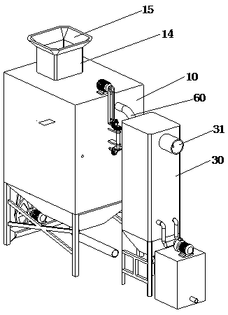
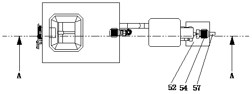
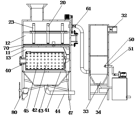
The invention discloses a sludge treatment device for the chemical industry and belongs to the technical field of chemical equipment. The sludge treatment device comprises a treatment tank, a sludge deodorizing mechanism, a purification tower, a sludge dewatering mechanism and a waste gas purification mechanism. A splitter plate is arranged inside the treatment tank to divide the inside of the treatment tank into a purification chamber and a dewatering chamber. The sludge deodorizing mechanism comprises a mixing module, a sludge scrapping module and two lamp holders. A sterilizing lamp is arranged on the lamp holder. The top of the treatment tank is provided with a pipeline. An exhaust fan is arranged inside an outlet pipeline. The invention has the following beneficial effects: through the sludge deodorizing mechanism, sludge in the purification chamber can be stirred to fully mix the sludge and a purifying agent, sludge on the inner wall of the treatment tank and on the top of the splitter plate also can be scrapped off; and through the waste gas purification mechanism, waste gas which is introduced into the purification tower can be sprayed and purified, and the purifying agentcan be recycled to save the resources.

Description

technical field [0001] The invention relates to the technical field of chemical equipment, in particular to the technical field of chemical equipment. Background technique [0002] Most of the existing industrial sewage is directly discharged into the environment, which seriously pollutes the environment. Moreover, there is a large amount of sludge in the sewage. When the sewage is discharged, the sludge is easy to settle down and remain in the equipment, which increases the cleaning of the equipment. It is difficult, and it affects the service life of the equipment, and when the sewage generated by industrial production is directly discharged into the environment, it is easy to affect the crops and the ecological environment, causing serious pollution. The conventional separation method is to use a filter to filter or settle the sludge, but the separation efficiency is not high, and there is still a large amount of water in the separated sludge, which affects the subsequent...

Claims


Application Information

Patent Timeline
Patent Type & Authority Applications(China)
IPC IPC(8): C02F11/14C02F11/121B01D53/18B01D53/04
CPCB01D53/04B01D53/18C02F11/121C02F11/14
Inventor 王子腾
Owner 王子腾
Why Eureka
Eureka Blog
Learn More