
An energy-saving building water circulation system

A water cycle and energy-saving technology, applied in waterway systems, buildings, sewage discharge, etc., can solve problems such as safety hazards and poor water quality in underground pools, and achieve the effect of avoiding safety hazards and maintaining water quality

Active Publication Date: 2021-04-30
CHONGQING CONSTR NINTH ENG
View PDF11 Cites 0 Cited by
  • Summary
  • Abstract
  • Description
  • Claims
  • Application Information

AI Technical Summary

Problems solved by technology

[0005] The present invention intends to provide an energy-saving building water circulation system to solve the problems of poor water quality in underground pools and potential safety hazards in manual cleaning of underground pools in the prior art

Method used


Image

  • An energy-saving building water circulation system
  • An energy-saving building water circulation system
  • An energy-saving building water circulation system

Examples


Embodiment 1

[0036] Basic as attached Figure 1 to Figure 3 Shown:

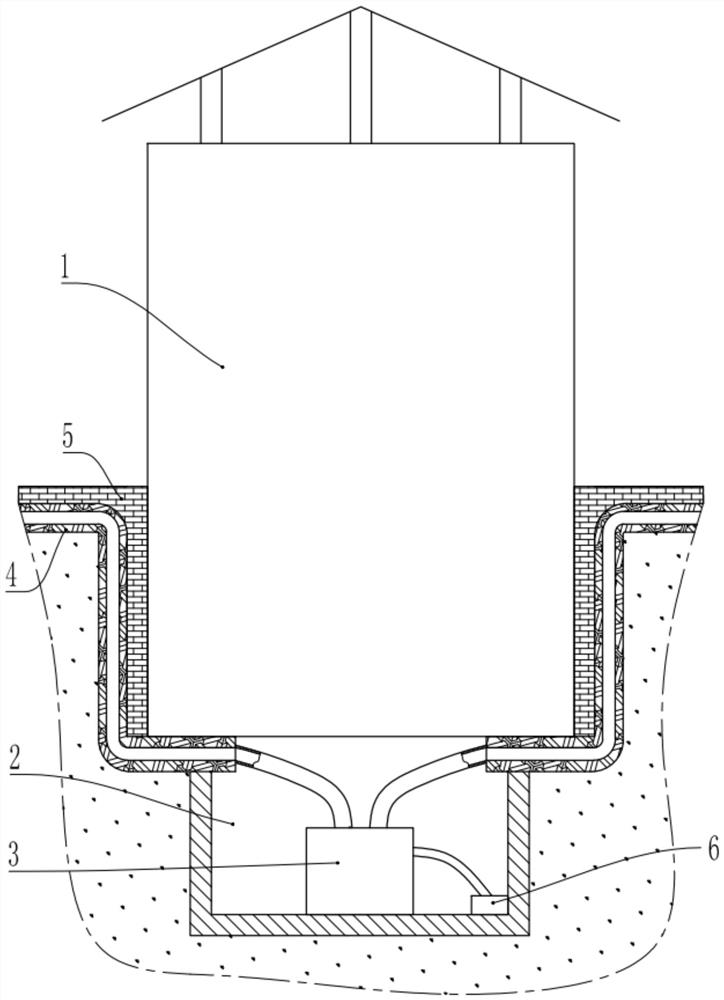
[0037] combine figure 1 , an energy-saving building water circulation system, comprising a building 1, an underground space 2 is arranged below the building 1, an underground pool 3 is arranged in the underground space 2, and a pool cover 12 is covered on the underground pool 3; 1 is provided with a blind ditch 4 around the place, and a permeable brick 5 is laid above the blind ditch 4. The underground pool 3 is provided with a water inlet and a drain; the blind ditch 4 is connected with the water inlet of the underground pool 3 through a laid pipeline, and the underground pool 3 is connected with a water pump 6 through a drain.

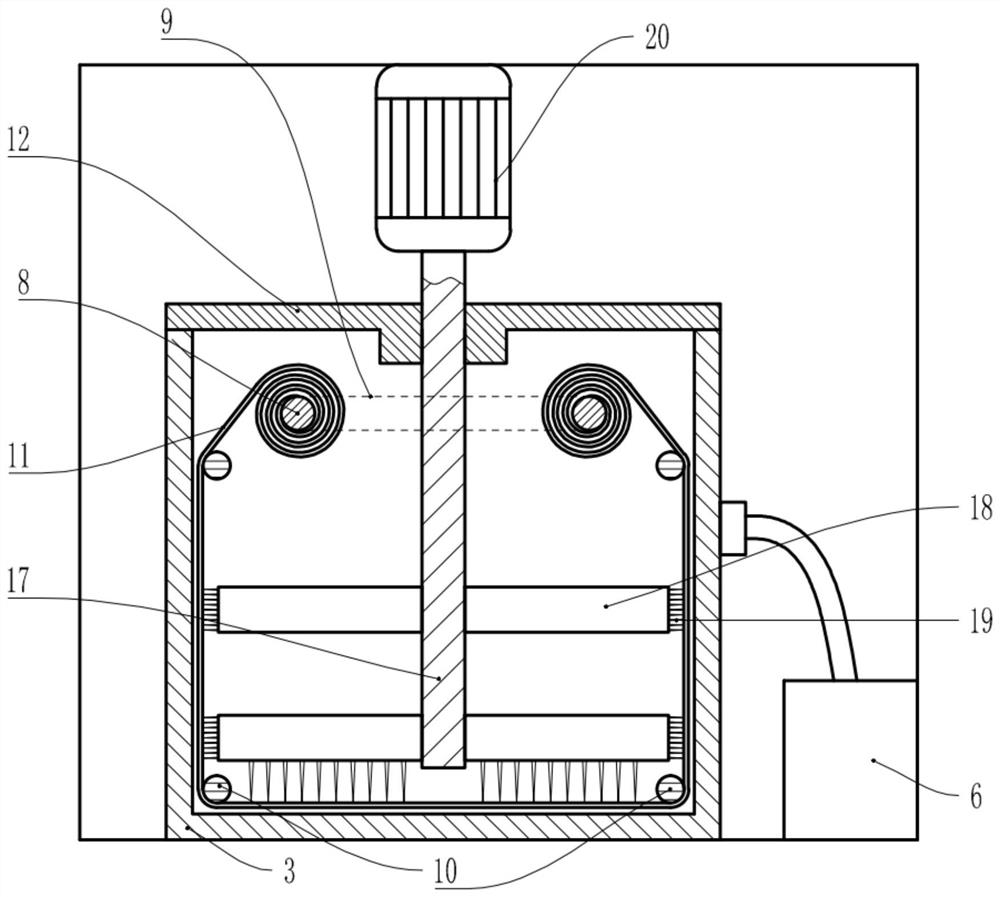
[0038] combine figure 2 The underground pool 3 is rotatably connected with two rotating shafts 8, the two rotating shafts 8 are rotatably connected to the side wall of the underground pool 3, the two rotating shafts 8 run through the side wall of the underground pool 3, and the two rotating ...

Embodiment 2

[0052] Example two such as Figure 4 and Figure 5 shown.

[0053] Embodiment 2 On the basis of Embodiment 1, an inverted T-shaped material storage channel 13 is provided on the pool cover 12, and the material storage channel 13 is located directly above the rotating shaft 8; the bottom of the pool cover 12 is rotatably connected to a baffle plate 14 , the baffle plate 14 can block the lower opening of the material storage channel 13, the rotation center shaft of the baffle plate 14 is covered with a torsion spring, one end of the torsion spring is fixed on the baffle plate 14, and the other end of the torsion spring is fixed on the pool cover 12; The baffle plate 14 is also integrally formed with a top plate, the end of the top plate is equipped with a rotatable roller 15, the baffle plate 14 can be pushed away by the mesh rope 11 wound on the rotating shaft 8 by the roller 15, and the material storage channel 13 is placed with Granular Activated Carbon16.

[0054] The spe...


PUM


Abstract

The invention relates to the technical field of water circulation, and specifically discloses an energy-saving building water circulation system, which includes a building, an underground space under the building, an underground pool in the underground space, two rotating shafts in the underground pool, and an underground space in the underground space. There is a first drive unit, which drives two rotating shafts to rotate; the underground pool is provided with guide wheels, and a mesh is wound on the rotating shaft, one end of the mesh is wound on one of the rotating shafts, and the other end of the mesh is Going around several guide wheels and finally on another shaft, the mesh sticks to the inner wall of the underground pool. The scheme solves the problems of poor water quality in the underground pool and potential safety hazards in manual cleaning of the underground pool in the prior art through the rotating shaft, the mesh and the guide wheel.

Description

technical field [0001] The invention relates to the technical field of water circulation, in particular to an energy-saving building water circulation system. Background technique [0002] Although the amount of water on the earth is huge, what can be directly used by people for production and life is very limited. At present, there are 16 provinces (autonomous regions and municipalities) in China whose per capita water resources (excluding transit water) are lower than the serious water shortage line, and 6 provinces and regions (Ningxia, Hebei, Shandong, Henan, Shanxi, Jiangsu) have per capita water resources Volume below 500m 3 . With the expansion of population and the rapid expansion of industrial and agricultural production, the shortage of water resources has become more serious. But even if there is a shortage of water resources, when the rainy season comes, the rainwater resources will greatly exceed the daily demand, causing waste. [0003] In order to rational...

Claims


Application Information

Patent Timeline
IPC IPC(8): E03F1/00E03F5/10E03F5/22B01D53/04E03B11/00
CPCB01D53/04E03B11/00E03F1/00E03F5/10E03F5/105E03F5/22
Inventor 周雪梅郭长春周建元郑曦
Owner CHONGQING CONSTR NINTH ENG
Learn More